10 seconds examining the waveform on a scope tells you all you need to know.
It only takes glance.

10 seconds examining the waveform on a scope tells you all you need to know.
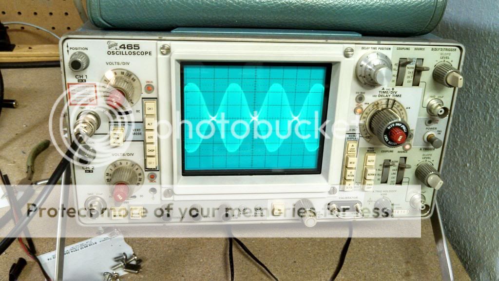
Exceeding 100% is a mathematical impossibility. Once you reach 100%, you have reached the limit of the channel's capability to handle more information. Any amount over 100% spills over into the adjacent channels, causing bleedover.
You cannot bend physical laws.
Exceeding 100% is a mathematical impossibility. Once you reach 100%, you have reached the limit of the channel's capability to handle more information. Any amount over 100% spills over into the adjacent channels, causing bleedover.
You cannot bend physical laws.
 all the while not exceeding 100% negative modulation. It is possible trust me. There is a difference between positive and negative peaks.
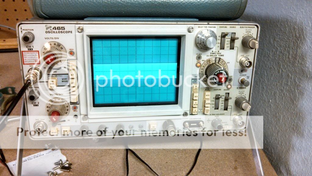
Edited in the carrier pic, CK.
~Cheers~
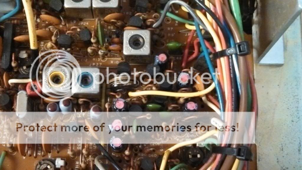
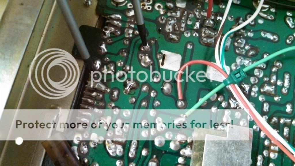
Then turning up the AMC w/o clipping the limiter should get a higher positive peak before it gets flat topped.Add a 10 uF 25 or higher volt electrolytic cap to these points: the positive leg goes to the trace that connects to pin 9 of the IC6 (the audio IC), and the negative leg goes to the R194/D63/R228 junction. This is the mod that compresses the negative modulation peaks and allows the average power to increase based on the modulation percentage.
")


