@tecnicoloco
Thanks for the handy information. Ill give it a try here, in the short future. And thanks for your kind thoughts, as well.
@loosecannon
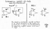
Short pins 6 and 7 - Build a "Vref voltage" which is 1/2 Vcc and apply that voltage to pin 5. Don't for get to by pass pin 5 to ground with a .1 poly cap.
Vref is nothing more than a voltage divider using the same values connected to Vcc- so like 10k and 10k or 47k and 47k. The voltage at junction of the two resistors is fed into pin 5 and by passed to ground via a cap.
@Whisky Flats
Yes, you can use the Precision Diode Detector in a 29. You can use it any AM receiver with a last IF of less than 500khz.
CBphreaker
thanks CBPhreaker,
i am still quite a novice when it comes to op amps and really any internals of ICs, so i usually have to use reference texts when putting the external part values and combinations together.
I must've really misunderstood the text i read! LOL
so, i'll put this in the thread for others that might be at my level of understanding or thereabouts.
what CBP is saying is that the unused side of a dual op amp such as the TL082 must be properly terminated to keep noise and other bad possibilities from occurring.
in this configuration, pin 5 needs to be fed with half the supply voltage.
both he and i, and i imagine the others building this circuit are using the 8 volts receive only voltage provided by pin 6 of the MB3756 voltage regulator in the MB8719 chassis.
so, pin 5 of the TL082 needs 4 volts fed to it.
to get this 4 volts, you use a voltage divider, which would consist of two resistors of equal value. let's use 10k ohm resistors.
so you connect one end of a 10k ohm resistor to the 8 volt supply rail (pin 8), and then connect another 10K ohm resistor to the free end of the first resistor. the other end of this second 10K resistor gets connected to ground (pin 4).
so what you have now is two 10K resistors in series, with one end connected to voltage, and the other end connected to ground.
now, where the two resistors meet, this is your 4 volt point, and this is what you would connect to pin 5 of the TL082. (right in between the two resistors)
the way a voltage divider works, if the two resistor values are the same, then the voltage in between the two resistors will be one half of the supply voltage.
now, you also want to add a .1uF poly cap from pin 5 to ground. this is for RF bypass.
then, you just short pins 6 and 7 together.
again, i am still vigilantly learning about op amps and digital circuits and such, so this is not meant to be a lesson, just putting the info out there for the future circuit heads to find.
Thanks again CBP, i believe this is the problem with the way mine sounds.
LC