• You can now help support WorldwideDX when you shop on Amazon at no additional cost to you! Simply follow this Shop on Amazon link first and a portion of any purchase is sent to WorldwideDX to help with site costs.

Cobra 148GTL-DX/SS360-FM SWR meter/Calibrate issue

Jan 5, 2019
24
9
13
55
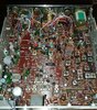
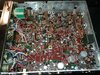
Hi all, I have a SWR meter / Calibrate problem here : s-meter works fine, but SWR and Calibrate will show the exact SAME readings whatever position I have on the calibrate potentiometer (max reading ca. 3/4 of scale).
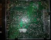
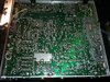
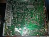
Everything worked fine prior the replacement of a few capacitors. I am careful whilst replacing capacitors and maybe i am not enough experienced in reading the schematic, but i have not found the SWR / calibrate circuitry to be on the path of electrolytic caps. Maybe a wrong solder joint somewhere?
Any hint would help find out what could have gone wrong meanwhile.
Thanks for your help! 73, Chris
 

Ok, just so you know, did you remember to re-hook the antenna lead pigtail back to the SO-239?

  • Don't worry, I've done it too! - :mad::censored::coffee::notworthy:!!!!

Then ANY SWR meter reading externally - no matter how good the antenna is, will show the antennas' SWR, EXTERNALLY - because the fault may lie INTERNALLY in the radio's RF output path in the path from the SWR meter to the Antennta jack...

So if you did any work or reheated a solder joint - even shifted that "coax thingy they use" for the SWR metering- re-check those areas

  • - the fault will not be present in a working system, the fault is occurring between the SWR meter, Front panel wiring and the rear panel jack.
Might need to re-install a cap if it's upsets the tuning that much...
 
Hello Andy and Nomad!
Thanks for your input, I will definitely check for any accidental solder bridge.
I already tried to get a look at my electrolytic caps solders, did not find anything wrong but will give it a look again.
Andy: happened to me too, but not this time, i first realized this issue while having the rig on a tuned antenna and then same on a 50 ohm dummy.
I check the resistors at the swr bridge, all OK ; I checked connections with my multi-meter at the switch and between the s-meter and the black wire to the PCB. All check OK.
I'll keep continue and put my results here.
Thanks again guys!
 
You know...

Those Super Stars and Cobra 148 DX models are extensively old - not just extremely old - but built differently than most radios - from that era.

They can be packed with parts and if issues like this come up, I can only think of disassembly and reassembly problems because you have to be careful with those lids when reassembling the clamshells back together.
 
Thanks Andy, yes definitely worth having in mind. My copy is a 1984 one, so a good old guy for sure, with grey electrolytes. I started to swap them, stopped when i realized this issue with the swr circuitry ; it definitely warns me to deal with this old guy like with eggs... Other than that loss of functionality it works extremely nice. Actually i had to reduce the power on SSB which was almost 20W to a safer and cleaner 14W ; you also should have seen the bias pots, they were on max, but why i don't know. Now they are in the 50mA range after I realigned the PA.
 
It's kinda nice to get a radio with original vintage parts, and rescue it.

They are keepers. Not just due to "nostalgic" in mind, they (Ahemn) work - er - Better, than many newer ones of today.

It's like buying a car kept in good condition, but not used much.

There's enough life left in it that makes it worth it - to keep it going...

Since you're doing the Re-cap, which is necessary, were you working along the back side when this cropped up?

The radio uses an insulated chassis - there are rear tabs that hold the board to the back panel so if the tabs - broke loose - there are open sections of trace runs that can open up that are part of it's "backplane" for RF grounding all along those screws.

Even the Final and Driver, this may indicate that they need to have their rear insulators that keeps them mounted and isolated from that back panel - the thermal paste may have started to break down - and even the SO-239 itself may need some reseating work too

- not sure if your radio is like mine it's had work done to it but maybe it will help.

This is what I've got...
upload_2020-8-10_12-25-11.pngCobra148-DXRearPaneldeatil.jpg

Hope this helps you...

At least these chassis' get a chance to get documented on this site...
 

Attachments

  • Cobra148-DXTopFront.jpg
    Cobra148-DXTopFront.jpg
    1.7 MB · Views: 12
  • Cobra148-DXTopMain.jpg
    Cobra148-DXTopMain.jpg
    2 MB · Views: 11
  • Cobra148-DXTopRear.jpg
    Cobra148-DXTopRear.jpg
    1.7 MB · Views: 15
  • Cobra148-DXTopSideLeft.jpg
    Cobra148-DXTopSideLeft.jpg
    2 MB · Views: 12
  • Cobra148-DXTopSideRight.jpg
    Cobra148-DXTopSideRight.jpg
    2 MB · Views: 11
  • Cobra148-DXTraceSideBottom.jpg
    Cobra148-DXTraceSideBottom.jpg
    1.8 MB · Views: 11
  • Cobra148-DXTraceSideLeft.jpg
    Cobra148-DXTraceSideLeft.jpg
    1.9 MB · Views: 12
  • Cobra148-DXTraceSideRight.jpg
    Cobra148-DXTraceSideRight.jpg
    1.9 MB · Views: 11
  • Like
Reactions: barefootindian
Thanks for the pictures Andy, nice radio is yours indeed, it's in pretty original condition. And I agree with the fact that it's so great to be able to go back in time and discover these good old rigs. I still believe these more reliable than today's Chinese SMD rigs.

Meanwhile i realized the radio, after keying TX for a short while (in my dummy load), suddenly starts to deliver more watts (like 7-8 watts AM instead of 5) and it makes sort of carrier on SSB (wattmeter deflects up to 11W instead of 14).
Now i start to think is there any ground issue somewhere, is it self-isolating?
I am sorry to struggle with what might be easy for some techs, and I must admit that I am not a tech and just a newbie in electronics and eager to have a nice vintage radio working, as other than that, it works.
I replaced until now 14 caps more or less on the audio side (from the power supply part to the mic side). They seem to be well soldered without bridge. But did I mess up something, although it's not my first recap, i have done several President Grant rigs without a single issue.
Back to the SWR bridge;
- i just think I have controlled everything with the exception of the diodes and the caps which sit between the rear side and the SWR board, I guess i'll have to de-solder them to test them. At the front everything seems to work properly.
- what I can't explain (=newbie me), is why am i getting the same readings on both the SWR and the CAL positions and whatever the position of the potentiometer (it goes 3/4 scale max).

I'll replace the SO239 socket (I have a nice one as a spare), it seems suspicious too and pretty worn.

I am stuck for now and without time to go further, I'll see tomorrow closer with a magnifier.
If you have any idea Andy, just feel free to throw them in here ;)
Thanks again,
Chris
 
Ok, hold on a sec...

upload_2020-8-10_21-2-58.png

Locate R255 and R256...off the SWR board...
upload_2020-8-10_21-14-52.png

You just may need to do some "elbow Grease"
and apply it to cleaning the switch - or the "pot"
of one of them has dirty contact, clean it up
see if it recovers...
You may want to do some cleaning of the potentiometers...that usually is the "bane" of the older analog design.

So locate all your radios "variable" on the main PCB, then go about cleaning them or at least reheating the solder joints to help "dry off" the dusty/dirty wiper arm contacts This may also help with the "climbing" wattages and some other unstable results.
 
Thanks Andy: I have controlled the resistors, and they are fine and like within 10% of 1kohm as per the schematics and I have also cleaned the switch and the rotary 5kohm potentiometer (contact 61 made electronics).
Checked continuity from the resistors R255 and R256 up to the switch and beyond and they all checked OK as per the schematics.
S-meter is working fine, shows strong signals, needle moves normally as it should.
My multi-meter is able to move the needle up to full scale (and alter it with the 5K LIN pot) when i position the test leads between the resistors (255 and 256) and the top of the PCB where the wires reach the switch.
So that's why i am stuck with this.
Not checked yet : SWR PCB (diodes, caps and resistors) as it may need un-mounting.
What I wonder is : what causes the reading to be pretty much the same whatever position of the switch CAL or SWR (it worked fine prior to swap a few caps) and no one altered the wiring, it's as per the schematics.
So that's it for the moment.
Chris
 
Well, it's which caps disturbed the original connection points?

Loose case to board screws - cold weak solering - flux remains - things like simple maintenance - for a lot of times, the ground plane (read earlier posts about the mountings and screws) There are "Mounting tabs" that can be either Riveted, or simple Ring lug (standoff types) that are not always SECURED, both physically and electrically, to the REAR Aluminum Panel.

There are Brass inserts into the chassis and as you saw in my photos, the anodizing got scraped so reconnection could be made to dissipate heat and bring electrical connection back to the original Square "U" shaped panels...

This also includes the front Panel to Front Faceplate screws.
 
Last edited:
Yep Andy thanks again, i'll be doing this after work, this afternoon, I planned to reflow the solder joints of the replaced caps, i'll reflow the old connections to the chassis, and the old solder joints along the SWR path see what happens (I have already re-tightened the screws to the chassis yesterday). I'll keep posting my results.
Has to do with dilatation as the rig is TXing fine during few minutes then warms up and does some self-oscillation sort of symptoms with sending more watts.
 
I remember in earlier days of BBS postings and Newsgroups - many people never realized that there are specific reasons and situations where replacing caps, you need the original performance parts as much as possible.

Capacitors although newer technology has made them better and smaller - but they also have changed their performance and structure to a point where finding OEM and putting them in there you may have to locate a source of these caps and hopefully they'll work to your benefit.

Capacitors in RF can also look like inductors - yes, the xL versus xC - to form an impedance path that can hinder the caps (parts own) ability to pass RF without sending DC thru it too.

As things age, so does their internal materials - some DISC caps are also semiconductor material - but are OXIDES of them and perform like caps. But as they age, the material worsens - as the oxide they are, continues the reduction process - reverting back to the ores they once originated from.

upload_2020-8-11_7-45-25.png
So they look very complex to RF and DC - and when they age, well, Electron Dementia (wandering) seems to take precedence. We don't know what that capacitor will look like in a decade.

So self-oscillation or ground loops will occur.

Just be ready for some erratic operation until you iron out the problems...

Here's some help...
upload_2020-8-11_8-10-43.png
 
  • Like
Reactions: hacksaw1340
There's more...

Depending on which area - they will oscillate...and it's related back to the cap values you used.

If you replaced the AM Regulator sections' "Regulation cap" you may want to recheck the value as well as other caps located in the TX's Final and Driver area...

If you worked on the AGC, there is another section you'll need to look into - RX input.
  • Sounds wild, but yes, a regenerative loop from the RX side being tuned and leaking IF "RF" can start a ringing effect.
  • It can even also be from those "Sil-pac" Silicone/Ceramic wafers used on the Final and Driver that can crack - and as they age, those insulator wafers add a different RF problem to this.
So yes, the low-frequency oscillations are occurring...and can even damage the radio while you work on it.

Have you gone to CB Tricks Website yet?

You may want to look for the Cobra 148-DX model (Is yours' 010 or 879?) CB Tricks in search engine to get the site and bookmark it...

If you worked on AGC cap, C44 - re-install OEM one back in.
See if SWR meter acts normally.

There is also this...you are having symptoms where SWR board is NOT Board ground, but CASE ground...
upload_2020-8-11_12-59-10.png

Compare this to the posts above - it's board which is mine...
Note symbol for GROUND...​

Let me know...
 

dxChat
Help Users
  • No one is chatting at the moment.
  • @ Wildcat27:
    Hello I have a old school 2950 receives great on all modes and transmits great on AM but no transmit on SSB. Does anyone have any idea?
  • @ ButtFuzz:
    Good evening from Sunny Salem! What’s shaking?
  • dxBot:
    63Sprint has left the room.