• You can now help support WorldwideDX when you shop on Amazon at no additional cost to you! Simply follow this Shop on Amazon link first and a portion of any purchase is sent to WorldwideDX to help with site costs.

Cobra 2000 Bias Adj. Help

HavaV10

New Member
May 24, 2023
67
13
8
56
Lake Havasu City, Arizona
I have a 1986 model year Cobra 2000. Final quit working. Just replaced the C1969 final with a used one that I had and works good. My question, I want to adjust the bias. My 2000 service manual mentions a TP3. There is a CRD on the pcb there and a hole but no post for a TP3. This is for the driver bias. For the final bias on my pcb board there is a TP7 & TP8. The TP7 post is not there (just a hole and no post) Wire isn't there for TP7 but there is a post and wire at TP8. Also saw a youtube video of a guy working on a Cobra 148 and it's service manual transmission alignment section says nothing about a TP3 like mine does. Kinda lost on what's going on here. My service manual is dated 1979. Thanks for any help.
 
Last edited:

There should be two wires with a spring-contact socket on the end, each plugged into a post on the circuit board. One for the driver and one for the final.

If you have only one, and a visibly empty pin visible next to where the one wire plugs in, that radio has had the "power jump" done to it. This consists of taking the bias-test wire and hooking it directly to the main DC power. This improves AM transmit PEP power just enough to see on the meter. Makes it the same as SSB peak power. Factory setup will cause AM peaks to always be just slightly less that sideband peaks. If there is a hole where the second test point pin should be, this must be what's been done. Somewhere we must have a picture showing the final bias-test wire. Taking it loose for where it's soldered to the main power will be necessary to insert a meter in line with the final's collector circuit.

And I forgot the "TP" numbers decades ago, I'm used to going by simple recognition.

73
 
  • Like
Reactions: unit_399 and NZ8N
There should be two wires with a spring-contact socket on the end, each plugged into a post on the circuit board. One for the driver and one for the final.

If you have only one, and a visibly empty pin visible next to where the one wire plugs in, that radio has had the "power jump" done to it. This consists of taking the bias-test wire and hooking it directly to the main DC power. This improves AM transmit PEP power just enough to see on the meter. Makes it the same as SSB peak power. Factory setup will cause AM peaks to always be just slightly less that sideband peaks. If there is a hole where the second test point pin should be, this must be what's been done. Somewhere we must have a picture showing the final bias-test wire. Taking it loose for where it's soldered to the main power will be necessary to insert a meter in line with the final's collector circuit.

And I forgot the "TP" numbers decades ago, I'm used to going by simple recognition.

73
ok thanks, you know your radios! I got the bias adjusted on the driver (30ma) but not the final only because the wire isn't there anymore. I guess I won't know the bias of the final, we'll see how long that final lasts. The bias final VR is at position 1 o'clock
 
The TP3 test point you are seeing in your manual is the same as my manual, and I knew long-long ago that it was a miss print in the manual, it should have read TP8.
Tp8 is the test point for the driver Bias adjustment.

Not knowing this you are trying to go by your manual, I can understand why you think TP3 is your test point.

TP3 is part of the synthesizer alignment, best to know what you are doing before you start messing with those adjustments.

Sometimes the service manual can be vague, but TP3 must be used when aligning the synthesizer circuit, and not the final section.

As nomadradio said, if TP7 is missing then the radio was converted to "Volt"(known as "Volting") the final in AM mode, or putting the full power supply voltage to where 6 volts or so should be in AM mode.

I had to edit the following..............
To adjust the final Bias:
You will have to unsolder the TP7 wire. It's the Green colored wire connected at L39, just follow it to the other end where it's going directly to the power supply voltage, and unsolder it there.

I hope that knowing this now helps you to get the radio going.
 
Last edited:
  • Like
Reactions: NZ8N and HavaV10
The TP3 test point you are seeing in your manual is the same as my manual, and I knew long-long ago that it was a miss print in the manual, it should have read TP8.
Tp8 is the test point for the driver Bias adjustment.

Not knowing this you are trying to go by your manual, I can understand why you think TP3 is your test point.

TP3 is part of the synthesizer alignment, best to know what you are doing before you start messing with those adjustments.

Sometimes the service manual can be vague, but TP3 must be used when aligning the synthesizer circuit, and not the final section.

As nomadradio said, if TP7 is missing then the radio was converted to "Volt"(known as "Volting") the final in AM mode, or putting the full power supply voltage to where 6 volts or so should be in AM mode.

I had to edit the following..............
To adjust the final Bias:
You will have to unsolder the TP7 wire. It's the Green colored wire connected at L39, just follow it to the other end where it's going directly to the power supply voltage, and unsolder it there.

I hope that knowing this now helps you to get the radio going.
thanks Frank, I'm going to leave the radio the way it is. I'm not a tech but know some. So TP3 is a typo in my service manual? Wow ok thanks for your valuable input. I appreciate it.
 
The TP3 test point you are seeing in your manual is the same as my manual, and I knew long-long ago that it was a miss print in the manual, it should have read TP8.
Tp8 is the test point for the driver Bias adjustment.

Not knowing this you are trying to go by your manual, I can understand why you think TP3 is your test point.

TP3 is part of the synthesizer alignment, best to know what you are doing before you start messing with those adjustments.

Sometimes the service manual can be vague, but TP3 must be used when aligning the synthesizer circuit, and not the final section.

As nomadradio said, if TP7 is missing then the radio was converted to "Volt"(known as "Volting") the final in AM mode, or putting the full power supply voltage to where 6 volts or so should be in AM mode.

I had to edit the following..............
To adjust the final Bias:
You will have to unsolder the TP7 wire. It's the Green colored wire connected at L39, just follow it to the other end where it's going directly to the power supply voltage, and unsolder it there.

I hope that knowing this now helps you to get the radio going.
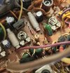
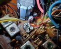
Also the wire has been removed between L39 and TP7. It's not there. Should this be put back to stock configuration? So how is power being sent to the final? I'm assuming it's being supplied 12V instead of 8V cause the wire isn't there.
 

Attachments

  • 20230806_122406.jpg
    20230806_122406.jpg
    1.1 MB · Views: 8
  • thumbnail.jpg
    thumbnail.jpg
    289.5 KB · Views: 8
The infamous RWOB...

This doesn't cause severe harm to the Radio - in fact many have had it done to prolong the life of the original AM Regulator Pass transistor used in that radio.

Although if left at 4 watts and AMC set between 70% ~ 90% mod - this RWOB (Red Wire On Bottom) mod was never needed. SSB 12W PEP - thru the ALC - the peak surges of power required - this worked well enough and many whom used Bi-polar (BJT) Amps - find the quality of audio from these radios - if left stock - does a far better job in audio reproduction even though it is in Class C - than many of todays radios.

The using the RWOB effort, you lost part of your Modulation envelope symmetry, the Final was never "modulated". Versus the keeping it stock and let the AM Regulator Pass Transistor power it, was to also preserve a Modulation symmetry effect that is used in Class D setups like the Cobra 2000, 148 and Grant series uses.

You don't lose a lot using RWOB, but the full overall modulation effect is then imposed and dependent on the Driver, which is a 2166 - and is now obsolete and also unobtainium as well.

Don't push it.
 
HavaV10,
The pictures you've posted do not show the bottom side (trace side) of the radio, could it possibly be located at the L39 trace?
As in the RWOB, as explained by Handy Andy, a red wire (or any wire) that goes to the L39 trace from a 13.8v source.
 
  • Like
Reactions: HavaV10

dxChat
Help Users
  • No one is chatting at the moment.