• You can now help support WorldwideDX when you shop on Amazon at no additional cost to you! Simply follow this Shop on Amazon link first and a portion of any purchase is sent to WorldwideDX to help with site costs.

Cobra 2000 GTL questions/ help needed

Crambone

Well-Known Member
Jan 22, 2019
489
156
53
55
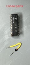
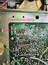
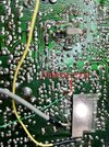
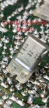
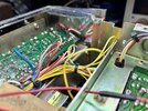
i picked up a Cobra 2000 GTL knowing it wasn’t tested but for the price I figured the speaker alone was worth the purchase. Did a normal once over, correct fuse, nothing inside burnt… but I did find 2 loose parts inside, never a good thing. I included a few pics of what I see inside. It looks to have a channel mod with 3 position switch in the aux spot. One wire is off, not a big deal if I get it working I am removing the mod. To my surprise it receives great but no TX.
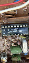
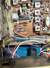
here are some pics on the inside.
 

Attachments

  • IMG_0385.png
    IMG_0385.png
    7.5 MB · Views: 12
  • IMG_0381.jpeg
    IMG_0381.jpeg
    351.9 KB · Views: 11
  • IMG_0382.png
    IMG_0382.png
    8.2 MB · Views: 13
  • IMG_0384.jpeg
    IMG_0384.jpeg
    2.1 MB · Views: 13
  • IMG_0373.jpeg
    IMG_0373.jpeg
    1.2 MB · Views: 13
  • IMG_0377.jpeg
    IMG_0377.jpeg
    3.1 MB · Views: 13
  • IMG_0374.jpeg
    IMG_0374.jpeg
    1.5 MB · Views: 13
  • IMG_0375.jpeg
    IMG_0375.jpeg
    1.3 MB · Views: 12
  • IMG_0383.jpeg
    IMG_0383.jpeg
    406.3 KB · Views: 11
  • IMG_0376.jpeg
    IMG_0376.jpeg
    1 MB · Views: 12

At least they gave you the original PLL (MB8734) if you want to change it back to stock.

No idea where that diode came from. Since it doesn't TX you could make sure you're getting the +8V out of the regulator in TX mode. Maybe step through the signal chain from the VCO to the final to see where the signal dies and then look for a missing diode around that circuit. Even if it's not from that part of the board, though, you'll still have at least isolated your problem somewhat.
 
  • Like
Reactions: Crambone
At least they gave you the original PLL (MB8734) if you want to change it back to stock.

No idea where that diode came from. Since it doesn't TX you could make sure you're getting the +8V out of the regulator in TX mode. Maybe step through the signal chain from the VCO to the final to see where the signal dies and then look for a missing diode around that circuit. Even if it's not from that part of the board, though, you'll still have at least isolated your problem somewhat.
I’m new to this so not sure where to check for the +8v? I did notice the PA works. I think I may need to print out a larger schematic I hate following on a iPad.
 
Your 2000 should have a chip labelled MB3756. That's your voltage regulator for the +8V receive and transmit voltages. In receive you should have +8V on pin 6 and 0V on pin 8. Which it sounds like you do. In transmit, you should have +8V on pin 8 and 0V on pin 6.

I'm assuming the voltage coming into that chip is OK, since receive is working.

And, yes, get as large a printout as you can as long as it's clear. Your eyes will thank you.
 
the diode is from the clarifier mod.
the brown wire is also from the clarifier mod.

if clarifier is working properly you can leave these two things alone.

as TM86 posted, check the voltages on the MB3756 paying close attention to the voltages on pins 6 and 8 in RX and TX. they should both change state.
LC
 
  • Like
Reactions: TM86
When you said "no transmit", I'll assume that this is because you don't see any wattmeter reading when keying the mike.

Do you have another radio to tune in the same channel the 2000 is on and listen for a weak signal that won't kick the wattmeter? A coax jumper on the monitor radio gets the sleeve at the far end backed off from the plug. This gets you a half-inch long "sniffing" antenna you can poke into the 2000, and see if it picks up a weak transmit signal.

There are enough different places for the transmit to shut down, that it's important to know if a transmit signal is being generated in the first place. If not, you can usually ignore the power sections that the "change the final" crowd point you to.

And if you do hear a weak signal, you can use the S-meter reading to see that tuning slugs in the transmit circuits are peaked.

Way too many radios get "screwdrivered off the air", a casualty of someone turning adjustments blindly.

73
the diode is from the clarifier mod.
the brown wire is also from the clarifier mod.

if clarifier is working properly you can leave these two things alone.

as TM86 posted, check the voltages on the MB3756 paying close attention to the voltages on pins 6 and 8 in RX and TX. they should both change state.
LC
I did as suggested and see the following voltages.
RX
Pin 6 8.2vdc
Pin 8 .5vdc

TX
Pin 6 .3vdc
Pin 8 8.2vdc

I also checked the “On the Air” bulb as it’s the only one not working and found something I believe to be strange. I tested the bulb at 12vdc and it works.
I put a dc meter on the wires from the radio and I am seeing 10vdc when in RX and then I key and see 13.4vdc
if I put the old or new bulb inline it doesn't light In RX or RX? I followed the 2 wires and they are going to the correct location. I just find this strange or does it have to do with the type of grounding. I did notice prior to anything that the ground is switched and not the positive? I found this out when I first found a bad on/ off button/ switch.
Some other voltage reading I took just for my own curiosity.
D52 7.9vdc
TR42 2SC945 both RX and TX no change
B 7.5vdc
E 13.3vdc
C 7.9vdc
TR41 2SC1418 both RX and TX no change
B 7.5vdc
C 13.3vdc
E 11vdc

TP7 & 8 11vdc RX and TX
 
When you said "no transmit", I'll assume that this is because you don't see any wattmeter reading when keying the mike.

Do you have another radio to tune in the same channel the 2000 is on and listen for a weak signal that won't kick the wattmeter? A coax jumper on the monitor radio gets the sleeve at the far end backed off from the plug. This gets you a half-inch long "sniffing" antenna you can poke into the 2000, and see if it picks up a weak transmit signal.

There are enough different places for the transmit to shut down, that it's important to know if a transmit signal is being generated in the first place. If not, you can usually ignore the power sections that the "change the final" crowd point you to.

And if you do hear a weak signal, you can use the S-meter reading to see that tuning slugs in the transmit circuits are peaked.

Way too many radios get "screwdrivered off the air", a casualty of someone turning adjustments blindly.

73
Nomad, I used both a wattmeter with 1watt slug and another radio as suggested and see and hear nothing Anywhere I placed the coax end.
 
hear nothing Anywhere I placed the coax end.
The Tx light staying dark is a clue. It gets activated by completing the ground side of the bulb circuit. The 'hot' 12-Volt side is always connected.

Time to check pin 8 of the MB3756 chip. Should be zero Volts DC in receive, and show 8 Volts DC while transmitting. If it won't the chip may or many not be bad, but at least you'll be closer to the fix.

73
 
Last edited:
The Tx light staying dark is a clue. It gets activated by completing the ground side of the bulb circuit. The 'hot' 12-Volt side is always connected.

Time to check pin 8 of the MB3756 chip. Should be zero Volts DC in receive, and show 8 Volts DC while transmitting. If it won't the chip may or many not be bad, but at least you'll be closer to the fix.

73
it does receive in AM, LSB & USB.

MB3758 shows the following
RX
Pin 6 8.2vdc
Pin 8 .5vdc

TX
Pin 6 .3vdc
Pin 8 8.2vdc
 
the voltage on TP7 and TP8 should be less than 11 volts in AM mode.
it should also vary when you turn VR10.

what voltages are you seeing on TR35 in both RX and TX?
LC
 
Last edited:
  • Like
Reactions: Crambone
This is where a 'scope pays for itself to anyone who does this a lot.

Finding a DC-voltage fault is great, since this will usually cause loss of signal, whether in the receiver or transmitter.

But if the fault is in a part that doesn't disrupt any normal DC voltages, it becomes necessary to follow the signal that's being lost. In this case the transmit signal.

Any time there is no transmit signal, even a weak one you can 'sniff' with a spare radio, peoples' eyes will focus on IC5, the "S042P" transmit mixer chip. This is where the 7.8 MHz carrier (or sideband) gets mixed with the 35 MHz PLL's vco. The 27 MHz signal originates in this part.

And they almost never fail. Really sounds as if one of the two inputs to this chip has gone missing.

But which one? This is much more common in my experience. IC5 failure is a once-every-few-hundred radios kind of fault, if even that often.

DC-voltage measurements will lead you to an "easy" fault. But this one is sounding less easy every time a new DC voltage gets checked, and reads like it should.

the voltage on TP7 and TP8 should be less than 11 volts in AM mode.

This will be true when the driver and final have a drive signal, and pull normal current from the AM modulator circuit. But when there is no carrier drive, the final and driver don't draw very much collector current. R193 will drive up the voltage reading on those two test points when AM carrier drive is lost. The reading he saw makes sense, considering R193.

73
 
Last edited:
  • Like
Reactions: loosecannon
This will be true when the driver and final have a drive signal, and pull normal current from the AM modulator circuit. But when there is no carrier drive, the final and driver don't draw very much collector current. R193 will drive up the voltage reading on those two test points when AM carrier drive is lost. The reading he saw makes sense, considering R193.

73

noted.

I remember Andy talking about R193 and what it does but had completely forgotten to consider it.
thank you for the clarification.
LC
 
This is where a 'scope pays for itself to anyone who does this a lot.

Finding a DC-voltage fault is great, since this will usually cause loss of signal, whether in the receiver or transmitter.

But if the fault is in a part that doesn't disrupt any normal DC voltages, it becomes necessary to follow the signal that's being lost. In this case the transmit signal.

Any time there is no transmit signal, even a weak one you can 'sniff' with a spare radio, peoples' eyes will focus on IC5, the "S042P" transmit mixer chip. This is where the 7.8 MHz carrier (or sideband) gets mixed with the 35 MHz PLL's vco. The 27 MHz signal originates in this part.

And they almost never fail. Really sounds as if one of the two inputs to this chip has gone missing.

But which one? This is much more common in my experience. IC5 failure is a once-every-few-hundred radios kind of fault, if even that often.

DC-voltage measurements will lead you to an "easy" fault. But this one is sounding less easy every time a new DC voltage gets checked, and reads like it should.


This will be true when the driver and final have a drive signal, and pull normal current from the AM modulator circuit. But when there is no carrier drive, the final and driver don't draw very much collector current. R193 will drive up the voltage reading on those two test points when AM carrier drive is lost. The reading he saw makes sense, considering R193.

73
I will Borrow a scope today and check the IC5 inputs
 

dxChat
Help Users
  • No one is chatting at the moment.
  • @ Wildcat27:
    Hello I have a old school 2950 receives great on all modes and transmits great on AM but no transmit on SSB. Does anyone have any idea?
  • @ ButtFuzz:
    Good evening from Sunny Salem! What’s shaking?
  • dxBot:
    63Sprint has left the room.