• You can now help support WorldwideDX when you shop on Amazon at no additional cost to you! Simply follow this Shop on Amazon link first and a portion of any purchase is sent to WorldwideDX to help with site costs.

Cobra 2000 no modulation.

If you measured ohms from the mic connector pin 1 to pin 2 I wouldn't expect to see anything other than 1K plus a tiny bit from the resistance in L403 and would not expect to see a difference when adjusting the mic gain pot. Essentially pins 1 and 2 go to opposite outer ends of the pot so you are measuring the full value of it.

Do you have any test equipment? Things that might help here... audio generator and scope or signal tracer?
 

Attachments

  • Screenshot from 2024-01-25 17-24-31.png
    Screenshot from 2024-01-25 17-24-31.png
    62.2 KB · Views: 5
  • Like
Reactions: Cable Guy
If you measured ohms from the mic connector pin 1 to pin 2 I wouldn't expect to see anything other than 1K plus a tiny bit from the resistance in L403 and would not expect to see a difference when adjusting the mic gain pot. Essentially pins 1 and 2 go to opposite outer ends of the pot so you are measuring the full value of it.

Do you have any test equipment? Things that might help here... audio generator and scope or signal tracer?
Hey Guitar,
Have all that and i'm currently going after the trace from the audio circuit off pin 1 to see where i'm loosing the signal.
 
Hey X Racer.
No AM modulation, It has AM dead key watt's on watt meter, it's on frequency when monitoring through a freq counter, No SSB transmit (Since no modulation) and nothing going pot the pa jack to a speaker while in PA mode.
No movement on the modulation meter, Mic work's on the mic tester.
No AM transmit power increase when sending a tone into the mic from the B&K 1040 or whistling into mic, So with no modulation getting into the radio, then no SSB power output.
Not to sound stupid, you say check/change the Audio IC chip, You referring to IC6, TA7222P? I'll run voltage checks on the IC6 and look for a replacement part, Not too fond of NTE part's and Mouser doesn't stock the TA7222P. Dunno about ebay with all the fake part's around these day's
 
Further ohm testing the pin's 1 and 2 of the mike socket, something just didn't jive. I have a Cobra 138XLR in my collection and pulled the bottom cover and compared it to this 2000, The 138 has the shield going to the ccw terminal, Audio from the mike going to the center and the center conductor of the shielded wire going to the cw terminal.
On this 2000 the shield is in the ccw terminal, the center conductor of the shielded wire goes to the center and the audio from the mike goes to the cw terminal. I pulled the dyna mike control and i could tell the wires had been swapped because the wires were just soldered to the terminal's and not wrapped around the holes in the terminal.
I swapped the audio wire to the center terminal and the center conductor of the shield to the ccw terminal. Now when i ohm check the 1 and 2 wires going to the mike socket i get the same reading's that Handy Andy posted earlier instead of always getting the 1,040 ohm's no mater where the dyna mike control was turned.
 
Ok, I'm here, got a photo of what you're up against?

And to help check, try the PA function - if you get audio to the PA jack there, then the wiring of the mic itself is not the problem - it may be in a failed cap onto a mod for talk back that was not done/undone properly.

The missing audio from the SSB side, may also indicate a blown diode from the ALC and AMC - they may be fighting each other.
1706574667545.png
They are supposed to work "separate" from each other, so when in AM, the carrier and envelope power doesn't swamp the ALC into thinking it's time to clamp - unless it has to - but that is a different story in another thread elsewhere.

It may be prudent to look around and see if other threads dealing with lost mic audio can help you find the yellow brick road back to the Emerald city and once there - key it up and put the audio in the cherry patch right next to the "Electric" lolly-pop kids..
 
Thanks Handy Andy. I'm currently making a list to recap this radio and in the mean time I'm back to a tram D-201A tube socket replacement. As soon as i get the 2000 back on the bench, I'll get to checking out your suggestions
 
Ok!

Keep us posted, and just so you know, when you work around those 2000's they are a lot like Grant XL and the 148GTL from that vintage.

The main issue I see with the "measurement" looking the way it does, is because the Mic audio is a complete circuit in it's own. So it only grounds to itself and powers unto itself - via that mics' power in the element - be it dynamic or otherwise powered audio.

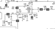
To help you a little more I'll post this schematic again here...
1706664692184.jpeg

The above is a guide to the RADIO side - not necessarily the PA side.

To help you also inclusive - is to ohmic check the Pins 1 and 2 not just on the mike plug side - but also at the Mic JACK side too.

That should always show some resistance across Pins 1 and 2 - so turn that Dynamike knob - watch the reading. Goes up to about 1K and stays there - but look at the output wiper arm terminal, as in inside the radio on the faceplate bezel - follow that to the radios own chassis - - test this wiper arm too - should be up to about 1K and down to near or at zero ohms - including a dead short - complete short to ground. This is where the Mic audio goes into that section - the Mic amp - so no PA? Start at that Dynamike output terminal and test to make sure Pin 1 gets to it, and it's variable to the Radio side - not the front panel side.

This brings up issues around "Balanced" and unbalanced - but they use a variable resistor and use the fixed resistor side across the Pin 1 and 2 - and the variable output is the level out to the Mic amp section.

That type of reading is important - the ground of the mic audio is at the same potential as the foil ground inside the radio and not the case - these radios are grounded in a fashion that the case is the same ground as the antenna (coax shield stuff) while the ground for the systems own electrical power - that 12V system, is isolated from CASE ground.

Now, check Pins 3,4 and 5 - to Pin 2 - Ohmic, check across those pins one should be at GROUND or OHMIC-ally be near zero to Pin 2 while another would be low- but ohmically about 8 ohms (your speaker return) - the other pin showing close to open, switches the MB3756 to toggle TX or RX. So the 3, 4 and 5 function like your normal RX/TX but also provide SPEAKER ground on RX mode - so ensure you have that Mic wired correctly.

These are "Hi-pot" UL tested - so they are a different beast.

Reading ohmic across from Coax ground and Radio Foil ground - Should not be any less than about 5K - any less than that may mean an issue with hazardous voltage isolation and the amount of current in it can poke you with is pretty good, on up to lethal dose if the tech gets careless.
 
Last edited:
Thank's Handy.
I took a break from the 2000 to recap my heathkit T-4 audio tracer and made up new lead's. Just so i can trace the audio path, Now when i test the audio path with the signal tracer, all is good and i hear my voice up to where the audio path goes into the board when i key the mike. The dynamike control increases and decreases the audio from the T-4 WHILE THE RADIO IS OFF, Once i turn the radio on, I loose the audio through the T-4.
I could shotgun some likely cap's, But the owner ok'd a cap job, So i ordered new Nichicon Cap's, Increasing the voltages to a higher size as needed and there all 108C* rated, So i'll see how it goes, Also a few Diodes and transistor's were ordered as well.
 
All electrolytic cap's replaced, Still no transmit modulation, I shot gunned a new TA7222O (IC6) in still inop.
I found a part's list in CB tricks https://cbtricks.org/radios/cobra/2000gtl/graphics/cobra_2000gtl_om_part_list.pdf And there are Tantalum cap's listed that i didn't see listed as Tantalum cap's in the Sam's book.
In message 12 in this post Andy posted a picture that say's to check C101, C100 and C103, I didn't replace unknowing they were Tantalum and i ordered all the electrolytic cap's
I have an assortment already in my Mouser cart to get these in my next order, Getting back to using the Heath kit T-4,
I did some audio probing and found that i loose the mike audio Downstream from the R126 resistor, Another words i have a weak audio signal on the Left side of R126 and no audio signal on the right side of R126,
I did ohm check R126 and it is 10K ohm's, and i do not have any audio probing Pin 4 of IC6. Until i receive the Tantalum cap's, I'll once again bail to the Tram D-201A and maybe even find a part i need for the team and order all at once.
Until next time, Scott from Colorado
 
  • Like
Reactions: Handy Andy
Morning Mr. Nomad
Cobra 2000,
Transmits carrier on AM.
Receives tone on AM and SSB.
No modulation on AM, SSB or PA
You remember that white Hygain radio you sold on e-bay? I was the buyer.
Cheer's Scott Colorado
 
Morning Mr. Nomad
Cobra 2000,
Transmits carrier on AM.
Receives tone on AM and SSB.
No modulation on AM, SSB or PA
You remember that white Hygain radio you sold on e-bay? I was the buyer.
Cheer's Scott Colorado
not AT ALL to irritate.....
simply to clarify.......

when you say "No modulation on AM, SSB or PA"

what I am interpreting is.... when the radio is set up and unkeyed, it will output sound for either AM or SSB ( I am assuming both USB & LSB)

but when you transmit.... AM, USB or LSB.... no modulation at all...

and, when you plug in a PA speaker, set it for PA and key up... nothing comes out... no voice, no feedback... nothing.....

Is that right?
(Thanks!)
 
Morning Mr. Nomad
Cobra 2000,
Transmits carrier on AM.
Receives tone on AM and SSB.
No modulation on AM, SSB or PA
You remember that white Hygain radio you sold on e-bay? I was the buyer.
Cheer's Scott Colorado
I have a "gift" for oversimplifying things. That said, I am going to dig around a bit in the schematic but here is my thinking..... (and I am more or less just thinking out loud to try to organize my thoughts!)

Below is a subsection of the block diagram.

If RCV works in any mode.... then I have to say that the AF AMP, AF POWER and speaker paths are all good.

The mic audio comes in through the MIC, then the MIC AMPS, then goes through the PA SWITCH and around to injection into the AF AMP.... and the AF AMP loops down in transmit to the AM POWER REG.

We know the AF AMP works (sound comes out of the speaker in RCV!)

We have indications that the AM POWER REG "is suspected of working". I say that because you do get a carrier in AM which indicates that the appropriate DC level is coming down through the REGULATOR and MODE SWITCH.

Closing in on it.....
the PA doesn't work (but we know the AF AMP does)
AM transmit doesn't work (but we know DC is getting through the regulator transistor

Neither of those two will work unless MIC AUDIO is getting to the AF AMP.

So, back at the MIC block.....
The first thing I am looking at is that link from MIC AMP that goes up to the BALANCED MODULATOR.

The block diagram indicates that this is "early" in the circuitry....
and we know THIS doesn't work.

So I am going into this with a single mission.... make SSB transmit work!

The BALANCED MODULATOR is not going to work if that audio doesn't make it up there......

The PA SWITCH block won't pass mic audio if there isn't any coming in.

I am going to study that MIC AMP box like nobody's business....because if the audio isn't going to the balanced modulator... there is a fair chance that THAT COULD BE the whole problem and once you fix it.... this thing will be on the air!

1707498861323.png
 
  • Like
Reactions: Shadetree Mechanic

dxChat
Help Users
  • No one is chatting at the moment.