• You can now help support WorldwideDX when you shop on Amazon at no additional cost to you! Simply follow this Shop on Amazon link first and a portion of any purchase is sent to WorldwideDX to help with site costs.

Cobra 2000 S Meter pegged to the right

Brian G

Active Member
Dec 21, 2020
313
33
28
56
The S meter pegs all the way to the right as soon as I turn on the radio. I had been doing some servicing on the RX a few weeks ago but this was not happening then that I saw. It does it even with no receive coming in. RF gain does nothing and it does it on PA and CB, AM and SSB. I did replace TR48 because I was getting basically same voltages across all 3 legs but that did not fix it and the replacement has the same readings. Could it be the meter itself or likely a bad component somewhere?
Thanks for any suggestions.
 
Last edited:

First thing I would do is find the source and drain leads of FET2 and bridge them together. Don't remember the physical layout, and the schemo offers no guidance. But the Sams diagrams do.

The problem sounds like runaway AGC. The automatic gain control circuit is responding as if a strong signal were present, reducing gain.

When there is no signal, FET2 is fully turned on and serves to pull base current away from the base of TR10. Makes the collector voltage go up, emitter voltage goes down. When there's a signal, FET2 pulls less current, and more current flows into the base or TR10. It then pulls TR10 collector voltage down, which pulls current from the base of TR48. This causes it to source current from its collector, which feeds into the meter trimpots VR1 and 2. The voltage drop across them feeds the S-meter through the mode selector switch.

When the S-meter is pegged, TR48 will show less than a Volt difference between the legs. Finding out what is causing TR48 to pull all that current is next.

If shorting across FET2 source to drain has no effect, it's probably not the problem. That part doesn't fail often , but nothing is fail proof.

This is not a common fault for that model, so it won't be a common fix.

73
 
No, I'm saying you should check the pinout before deciding which lead wire goes into which hole. If the new one has the pins in a different order from the factory part, legs will have to be crossed so the correct lead goes into the correct hole.

73
 
No, I'm saying you should check the pinout before deciding which lead wire goes into which hole. If the new one has the pins in a different order from the factory part, legs will have to be crossed so the correct lead goes into the correct hole.

73[/QUOTE
 
Last edited:
So it looks like it is FET2 is not the problem. I’ve made some headway just cleaning up the contacts. The meter is not pegged anymore but it it still is around 5 s-unit mark.
Couple of things. Here are voltages at various points:
FET2: 6.9, 1.6,0 (these seem low)
TR48: 4.7, 1.57,4.1. (Those are quite high vs spec )
TR10: 1.0, 4.8, 1.6(these are off vs spec too)
If I touch my finger to the drain of FET2 , the meter falls to zero and the voltages drop at TR48 to 3.9,0 and 3.6 at tr10 they change to 1.3, 3.9, 2.0 but when I take my finger off it slowly creeps back up to 3-5 on the meter again. Some some kind of downstream effect.
That indicate something still wrong? Could the meter be damaged from being pegged so hard?
 
Last edited:
No NOT the meter, the FET...your proximity finger acts like an antenna - changes the loading on the FET, lessening the "Sensitivity" effect the Gates push into the Source to Drain.

Tells me the FET is leaky, got a spare?

Else on TR16, there is a tap from the Xtal filter that sends part of this IF to the TX side for mixing - comes after the AN612 stuff - which is that section doing ok? Referring to TR16 area - because the IF from there goes to L48 which is 1/2 the TX signal stuff - so the other part arrives to L48 from the PLL side of things.
 
Last edited:
Oh, hold off then,,

IF FET is good, the touching of the Drain adds body capacitance - so it's reacting. In which particular way it's hard to tell.

So the S-meter - as @nomadradio pointed out, is a balance of input to output - thru the use of a balanced bridge the FET looks at the signal arriving to a reference signal level. The bridge helps the FET decide which to act upon or not - the signal present - which affects TR10 and the AGC side as well as TR16 the IF amp just past the FT3 Xtal mess.IT also sets Squelch to open or close (TR12 an TR13) - and how aggressively to stay open when a signal is present

Which makes me wonder if you are getting leakage from that Xtal filter network FT3 - if something is off kilter in it - sending signal thru when it shouldn't .would upset the balanced bridge.

But again I look at assembly first you've been working on it, coudl you have undone a wire that needed to go somewhere?

See below...
upload_2021-2-20_18-22-29.png
The ANL/NB SWR/MOD/CAL board provides a grounding point - if the front panel has had some work done - you need to check on this.
 
Oh, hold off then,,

IF FET is good, the touching of the Drain adds body capacitance - so it's reacting. In which particular way it's hard to tell.

So the S-meter - as @nomadradio pointed out, is a balance of input to output - thru the use of a balanced bridge the FET looks at the signal arriving to a reference signal level. The bridge helps the FET decide which to act upon or not - the signal present - which affects TR10 and the AGC side as well as TR16 the IF amp just past the FT3 Xtal mess.IT also sets Squelch to open or close (TR12 an TR13) - and how aggressively to stay open when a signal is present

Which makes me wonder if you are getting leakage from that Xtal filter network FT3 - if something is off kilter in it - sending signal thru when it shouldn't .would upset the balanced bridge.

But again I look at assembly first you've been working on it, coudl you have undone a wire that needed to go somewhere?

See below...
View attachment 43241
The ANL/NB SWR/MOD/CAL board provides a grounding point - if the front panel has had some work done - you need to check on this.
I need to check a bit more but when I unsoldered the drain side, the problem went away. But not sure if that’s just because it’s ubsoldeered.
Oh, hold off then,,

IF FET is good, the touching of the Drain adds body capacitance - so it's reacting. In which particular way it's hard to tell.

So the S-meter - as @nomadradio pointed out, is a balance of input to output - thru the use of a balanced bridge the FET looks at the signal arriving to a reference signal level. The bridge helps the FET decide which to act upon or not - the signal present - which affects TR10 and the AGC side as well as TR16 the IF amp just past the FT3 Xtal mess.IT also sets Squelch to open or close (TR12 an TR13) - and how aggressively to stay open when a signal is present

Which makes me wonder if you are getting leakage from that Xtal filter network FT3 - if something is off kilter in it - sending signal thru when it shouldn't .would upset the balanced bridge.

But again I look at assembly first you've been working on it, coudl you have undone a wire that needed to go somewhere?

See below...
View attachment 43241
The ANL/NB SWR/MOD/CAL board provides a grounding point - if the front panel has had some work done - you need to check on this.
.[/QUOTE]
I need to check a bit more but when I unsoldered the drain side, the problem went away. But not sure if that’s just because it’s unsoldered.
 
Oh, hold off then,,

IF FET is good, the touching of the Drain adds body capacitance - so it's reacting. In which particular way it's hard to tell.

So the S-meter - as @nomadradio pointed out, is a balance of input to output - thru the use of a balanced bridge the FET looks at the signal arriving to a reference signal level. The bridge helps the FET decide which to act upon or not - the signal present - which affects TR10 and the AGC side as well as TR16 the IF amp just past the FT3 Xtal mess.IT also sets Squelch to open or close (TR12 an TR13) - and how aggressively to stay open when a signal is present

Which makes me wonder if you are getting leakage from that Xtal filter network FT3 - if something is off kilter in it - sending signal thru when it shouldn't .would upset the balanced bridge.

But again I look at assembly first you've been working on it, coudl you have undone a wire that needed to go somewhere?

See below...
View attachment 43241
The ANL/NB SWR/MOD/CAL board provides a grounding point - if the front panel has had some work done - you need to check on this.

nope that’s not it. I found the wire running between those 2 boards. I didn’t think it would be as I wasn’t working anywhere near those.
Here’s a question. See the pic. The one on the left is the one I pulled originally. It looks like a “regular” transistor. Black plastic top round in one side flat in the other. The one on the right is the new one. I had more like a metal top. And in the flat side has a little “lip” sticking out horizontally. They both say 2sk19. But could there be something different about them? This website makes it look like they are the same though. The legs are the same but could there be something with the IDSS values? My old one I think is the 3rd one from left. The new one is like the first 2 on the left.
https://2.bp.blogspot.com/-u1QOgjyr...DEEfvR7HM2k/s1600/2SK19_2SK192A_J-310_01S.jpg
 

Attachments

  • 89AE5814-92B0-4E31-83EE-186E6FE8BE41.jpeg
    89AE5814-92B0-4E31-83EE-186E6FE8BE41.jpeg
    1.3 MB · Views: 5
Last edited:
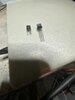
They are A BIT blurry

The one on the left, looks to be clone, the REAL package design was on the right...NOS

Both got wrapped into TO-92 style from the ISO conversion that makes China the big player it is now...no one else took the time to re-tool - they left their packages in old bins and warehouses to be gather up by collectors and repair personnel - the ones that tried to re-tool - never went back to make the OEM parts they used to - look at Motorola and Fairchild...

IT's (Right) "flared" for a reason these devices were originally designed to be recognized as small signal unique parts - so they did up various package designs before ISO standards arrived in the late 90's.

The "Flare" makes the part unique as in not to put parts in close proximity to package - hence the "lip" acts like a guard to keep components that could have their leads slide and touch the part - this was put on by various makers making FET or J-FET's - wanted to let others know of the output space on the board needed room to insert and not to have parts carrying signals close to the body, so it would not receive stray signals.

They also used these package designs to identify the kinds of substrate the part was, Germanium versus Silicon and even Selenium

But in your case...
upload_2021-2-21_8-58-48.png
Look at the "Letter" (A-B-C) designations.
These are showing High-gain "lot lettering" to show the level of Gain
Look on the bottom though.
The power dissipation (Idss) levels are what you need to be sure you select the part that operates
- within if slightly above - your lowest expected number.​


It's the Gain part, that may be your whole problem.
upload_2021-2-21_9-16-3.png

IF you're sure of your wiring, and can verify the tuning of L14 is correct - for L14's output not only captures the SSB signal, but offsets the Bridge to show RF - AND the IF is aligned correctly - the AM side of the Bridge and the "detuned" effect of L14 for AM (7.8MHz IF to 455kHz)) and SSB IF 10.7MHz - are NOT mixing together - throwing the leakage into the S-meter - you're issue may be gain - but when you work on a radio ,then the S- meter goes pegged, can't help but wonder; with the soldering iron hot, it touched something it shouldn't have.

Package:
This mess was during a transition between metal cased to Plastic epoxy - started in the 70's and as parts got obsoleted and NOS - they switched more and more to the epoxy case style but still had to keep the designs unique for identification of maker as well as proximity.

So the LEFT would be typical of the era, but the OEM part you're looking to use, is on the Right. Since they clone these - the Gain gives' away the effects of this cloning - you may have to reconsider finding a lower gain part or keeping the original in place until you're absolutely sure the FET was and is - truly damaged. As @nomadradio said, they don't "fail" - it's usually something upstream that shows up further down the strip it goes...(a good tune will help go a long way in proving this theory you have)

They still make metal case, but for military spec and EHF designs requiring a shielded, not just isolated - design.
 

dxChat
Help Users
  • No one is chatting at the moment.
  • dxBot:
    Tucker442 has left the room.
  • @ BJ radionut:
    LIVE 10:00 AM EST :cool:
  • @ Charles Edwards:
    I'm looking for factory settings 1 through 59 for a AT 5555 n2 or AT500 M2 I only wrote down half the values feel like a idiot I need help will be appreciated