Acquired a cobra 25ltd classic older model from eBay i recapped the radio, audio and carrier works great just have no recieve at all I hear a faint sound

You are using an out of date browser. It may not display this or other websites correctly.
You should upgrade or use an alternative browser.
You should upgrade or use an alternative browser.
-
You can now help support WorldwideDX when you shop on Amazon at no additional cost to you! Simply follow this Shop on Amazon link first and a portion of any purchase is sent to WorldwideDX to help with site costs.
-
A Winner has been chosen for the 2026 July 4th Retevis RA89R Giveaway! Click Here to see who won!
Cobra 25 Ltd classic
- Thread starter kaos513
- Start date
Then time to use the Tip of finger on tip of long reach 2mm Philips to act as the antenna and start your way from the back by the Detector thru 2nd IF, onto 1st IF - the section that doesn't give you any noise is suspect.
More than likely it may be a filter element (455 or 10.7 Muratas n' such) or loose coil wind in one of the many cans in there.
Came across several Cobras from the KEPC-1106 and 11xx series (the Classics as well as LTD's - discrete) that had separated coil winds inside their cans, Unsolder the tabs to the cans and pull off that shield - you'll see it stand out - like an unwound "whisker"
I don't have any "bad" ones to show so...

One side, the power side - is easy to catch, your DVM "dies" checking for voltage, it's the other side that sends it's signal to the input of the next stage you need to do a continuity check on.
Last edited:

Heres' the rub...
@kaos513 - You said you got Carrier and Audio - meaning that it does transmit.
So the only other thing to worry about is L16 - which if the Radio Transmits, you don't have issues with that.
The PLL SHIFTS 455kHz though, so that changes the coils that "peak" and therefore the output of signal from the PLL's VCO section. still arrives to L3 from L16 - only it's more closer to the IF image it needs to pass into the CF1 right by it. Past L3 going into L4 - it's the one with that 16MHz signal for that 1st IF (10.7MHz)
The other is the 10.240 it uses to knock down the IF to 455kHz, you wouldn't have Transmit if that were "out of commission" so the Xtal side seems to be ok, the PLL works...The RF Receive IF on the RX side (that 10.240MHz one) is peaked out at FET2 Leg thru C13 - FET receives power from L5 thru it's opposite leg. (Drain Gate Source - sort of thing)
So that leaves...
L1, L2 - L3 above, L4, L5 L6 and L7.
So it's why I mentioned take a finger and tip of a metal tool and make a low level antenna using body capacitance to offer some level of signal injection. Start at L7 and work your way up the strip back towards Noise Blanker and even L1 - the input.
Much of the strip should work, for if the 2nd and 1st IF's were aligned right, you'd have signal at least back thru to the FET at L3 - so what I suggest is to look further BELOW on the foil side.
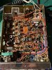
You may not have one in your '25 - but you then need to check FET1 (In the above photo it's Q24 - just above TP3) make sure your SK192 is working - why? C161 is part of TP3 - it divides down the RF presence off of L16. For if L16 was too strong, it can and will burn out Q24/FET1 from too much signal.
C161 may be "empty" in your Radio, look under the board for it - by TP3.

But you will on a PC-66 and PC-68
As C161

So look for C161 usually on the bottom side, so if you see it - make sure it's AFTER TP3 as far as signal tracing route FROM L16 - so it shares the same leg of the FET - other side of R6 - the body side that goes INTO the board.
Cobra 25's didn't need it per their idea, But for your sake, if the FET in either location L3 or L5 is blown, better put that C161 in and recheck C13 make sure it's in specs too...
@kaos513 - You said you got Carrier and Audio - meaning that it does transmit.
So the only other thing to worry about is L16 - which if the Radio Transmits, you don't have issues with that.
The PLL SHIFTS 455kHz though, so that changes the coils that "peak" and therefore the output of signal from the PLL's VCO section. still arrives to L3 from L16 - only it's more closer to the IF image it needs to pass into the CF1 right by it. Past L3 going into L4 - it's the one with that 16MHz signal for that 1st IF (10.7MHz)
The other is the 10.240 it uses to knock down the IF to 455kHz, you wouldn't have Transmit if that were "out of commission" so the Xtal side seems to be ok, the PLL works...The RF Receive IF on the RX side (that 10.240MHz one) is peaked out at FET2 Leg thru C13 - FET receives power from L5 thru it's opposite leg. (Drain Gate Source - sort of thing)
So that leaves...
L1, L2 - L3 above, L4, L5 L6 and L7.
So it's why I mentioned take a finger and tip of a metal tool and make a low level antenna using body capacitance to offer some level of signal injection. Start at L7 and work your way up the strip back towards Noise Blanker and even L1 - the input.
Much of the strip should work, for if the 2nd and 1st IF's were aligned right, you'd have signal at least back thru to the FET at L3 - so what I suggest is to look further BELOW on the foil side.
You may have too much IF presence - it drowns out your RF Amp...

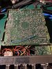
This pics from a PC-68 - see C161?
This pics from a PC-68 - see C161?
You may not have one in your '25 - but you then need to check FET1 (In the above photo it's Q24 - just above TP3) make sure your SK192 is working - why? C161 is part of TP3 - it divides down the RF presence off of L16. For if L16 was too strong, it can and will burn out Q24/FET1 from too much signal.
C161 may be "empty" in your Radio, look under the board for it - by TP3.
But you will on a PC-66 and PC-68
As C161
Cobra 25's didn't need it per their idea, But for your sake, if the FET in either location L3 or L5 is blown, better put that C161 in and recheck C13 make sure it's in specs too...
Last edited:
There's your part!

They used a 22pF - note it's location though, might want to clean that up - especially when they mount these in a close cluster of leads on the solder side.
Might want to check the "volume" of signal on TP 3...

If Signal level seems ok, be sure that FET1 is
even getting a signal - see above...
I've seen perfectly good radios shipped with a dead receive simply from that cap you see on the bottom of the board, got folded over by Assembly and it wound up chipping and then one of the plates sending a signal to the lead it's chipped on - usually somewhere it doesn't need to go,
Since this is a buffered signal - the radio's receive "died" - or just dead on Arrival - Transmit works because the signal attenuates, yes, but PAST TP 3 at the Leg of FET1 - so you might want to clean this area up and see it the RX recovers...
There are two ways this can occur, and one gives you a really strong TX signal - but no RX even though you have 10.240 and the 16MHz at that TP3 - did the cap suck the signal to ground or send it somewhere else?
They used a 22pF - note it's location though, might want to clean that up - especially when they mount these in a close cluster of leads on the solder side.
Might want to check the "volume" of signal on TP 3...
If Signal level seems ok, be sure that FET1 is
even getting a signal - see above...
Since this is a buffered signal - the radio's receive "died" - or just dead on Arrival - Transmit works because the signal attenuates, yes, but PAST TP 3 at the Leg of FET1 - so you might want to clean this area up and see it the RX recovers...
There are two ways this can occur, and one gives you a really strong TX signal - but no RX even though you have 10.240 and the 16MHz at that TP3 - did the cap suck the signal to ground or send it somewhere else?
IF you say you recapped it, Nice work.....all look OEM with some lifted traces...on the OEM side but look to be still attached to foil...
But you are aware the TDA9106 is on a header?

And found a spot I am not sure about...

But you are aware the TDA9106 is on a header?
And found a spot I am not sure about...
There's your part!
They used a 22pF - note it's location though, might want to clean that up - especially when they mount these in a close cluster of leads on the solder side.
Might want to check the "volume" of signal on TP 3...
View attachment 42273I've seen perfectly good radios shipped with a dead receive simply from that cap you see on the bottom of the board, got folded over by Assembly and it wound up chipping and then one of the plates sending a signal to the lead it's chipped on - usually somewhere it doesn't need to go,
If Signal level seems ok, be sure that FET1 is
even getting a signal - see above...
Since this is a buffered signal - the radio's receive "died" - or just dead on Arrival - Transmit works because the signal attenuates, yes, but PAST TP 3 at the Leg of FET1 - so you might want to clean this area up and see it the RX recovers...
There are two ways this can occur, and one gives you a really strong TX signal - but no RX even though you have 10.240 and the 16MHz at that TP3 - did the cap suck the signal to ground or send it somewhere else?[/QUOTE
Spot you found is good I did continuity testIF you say you recapped it, Nice work.....all look OEM with some lifted traces...on the OEM side but look to be still attached to foil...
But you are aware the TDA9106 is on a header?
And found a spot I am not sure about...
Pll Is on a socket
Tp3 has good signal using my scope
Brown wire goes to End of pll
Edit :changed cf2 back to original part
Attachments
Last edited:
I got it cheap I don't know if there was mods done or wires switched but some are close based on the wiring diagram
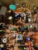
That one spot at X1 I pointed to right next to that B wire out - was looking Kinda iffy...The B wire goes to the Diode next to it by L5 CF2. The arrow I question - That is your main 10.240. by CA1 (your trimmer cap for X1) looks like some work was done below.
Are you able to get the Varactor at TP2 to be steady? As - is it adjustable voltage by tweaking L15 in RX mode?
If it isn't, look for 8 volts on the PLLs' Pin 8 in TX, then falls to or near 0V in RX. That tells the PLL to shift that 455kHz.

At the Same time - Run a Frequency counter on TP3 - make sure it's shifting too.
You look to have an older 9106 chip in a newer KEPC 25LTD PLL chip insert.
Due to the "drifting" in RX voltage lines, that voltage buffer resistor R58 in the NEWER 25's needs a pull up and DOWN resistor - so R58 Pull up - R150 Pull-Down.
They use R58, 4.7K - R150? 22K but you can easily use a 10K here to ENSURE that toggle.
Might want to try that...
Are you able to get the Varactor at TP2 to be steady? As - is it adjustable voltage by tweaking L15 in RX mode?
If it isn't, look for 8 volts on the PLLs' Pin 8 in TX, then falls to or near 0V in RX. That tells the PLL to shift that 455kHz.
At the Same time - Run a Frequency counter on TP3 - make sure it's shifting too.
You look to have an older 9106 chip in a newer KEPC 25LTD PLL chip insert.
Due to the "drifting" in RX voltage lines, that voltage buffer resistor R58 in the NEWER 25's needs a pull up and DOWN resistor - so R58 Pull up - R150 Pull-Down.
They use R58, 4.7K - R150? 22K but you can easily use a 10K here to ENSURE that toggle.
Might want to try that...
dxChat
- No one is chatting at the moment.