Installed with positive to ground, there is no reverse polarity. This is what happens.
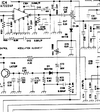
The transformer primary feeds DC to the finals. Since the audio is coming in on a tap (think autotransformer), the audio will cause the transformer output to the finals to go negative with respect to ground and we don't want that. The diode at the transformers output prevents the modulated transformer output from applying negative voltage to the finals.
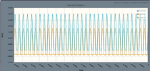
Now we have a situation where the output would look something like this without the AMC (note the negative clipping):
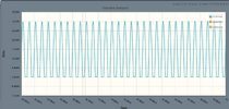
See how the peak voltage is about 30v (for this simulation)? Because it is an autotransformer, the audio is able to get the transformer output above 13v+13v (and well below 0v), which is good because this allows us to reduce the mic gain to combat negative clipping without going below legal limit on the peaks.
C73 blocks DC, so the audio waveform on the diode side of C73 becomes centered around the voltage established by R73 and R72. Now we have audio peaks that go below 0v for the AMC. It is these negative peaks that are rectified by D11 and applied to the PNP transistor (which then attenuates mic signal).
In this waveform, please note that I do not have the AMC connected to the audio input, so that means what you see is roughly what you get if the AMC is clipped. However, it serves to illustrate the negative voltage that is being generated on the capacitor. This is why these caps must have + on the radios ground, so when this negative AMC voltage is applied, the capacitor sees the correct (normal) polarity. That orange trace is why the caps are in with + to ground, because the other side drops below ground.
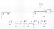
Again, as you can see in this schematic, I did nothing with the PNP transistor and the far left signal source does nothing. I was going to model the audio amp and feedback so it works but I dont have time today, so just ignore the 1khz source on the far left.
The VR lets you adjust the feedback so you can set it to the point the negative clipping just disappears.
The transformer primary feeds DC to the finals. Since the audio is coming in on a tap (think autotransformer), the audio will cause the transformer output to the finals to go negative with respect to ground and we don't want that. The diode at the transformers output prevents the modulated transformer output from applying negative voltage to the finals.
Now we have a situation where the output would look something like this without the AMC (note the negative clipping):
See how the peak voltage is about 30v (for this simulation)? Because it is an autotransformer, the audio is able to get the transformer output above 13v+13v (and well below 0v), which is good because this allows us to reduce the mic gain to combat negative clipping without going below legal limit on the peaks.
C73 blocks DC, so the audio waveform on the diode side of C73 becomes centered around the voltage established by R73 and R72. Now we have audio peaks that go below 0v for the AMC. It is these negative peaks that are rectified by D11 and applied to the PNP transistor (which then attenuates mic signal).
In this waveform, please note that I do not have the AMC connected to the audio input, so that means what you see is roughly what you get if the AMC is clipped. However, it serves to illustrate the negative voltage that is being generated on the capacitor. This is why these caps must have + on the radios ground, so when this negative AMC voltage is applied, the capacitor sees the correct (normal) polarity. That orange trace is why the caps are in with + to ground, because the other side drops below ground.
Again, as you can see in this schematic, I did nothing with the PNP transistor and the far left signal source does nothing. I was going to model the audio amp and feedback so it works but I dont have time today, so just ignore the 1khz source on the far left.
The VR lets you adjust the feedback so you can set it to the point the negative clipping just disappears.
Last edited: