• You can now help support WorldwideDX when you shop on Amazon at no additional cost to you! Simply follow this Shop on Amazon link first and a portion of any purchase is sent to WorldwideDX to help with site costs.

Cobra 29 Classic No RF on TX

Chris Lawrence

Active Member
Jul 9, 2021
83
40
28
Cobra 29 Classic No RF Power on TX. Doesn’t budge meter. Nothing on scope at the antenna jack.

TX turns red on key -up
Audio works with talkback
PA works
IC3 Pin 1 = 16.510MHz on RX
IC3 Pin 4 = 10.240 MHz on RX

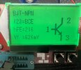
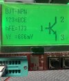
On TX: Base / Collector / Emitter
TR16 0v/8.0v/0.35v
TR15 0v/13.3v/0v
TR14 0v/13.3v/0v

Where should I go from here? What info can I provide?
 

Attachments

  • 9BEB8356-84FE-4341-AFD7-151DD7E8C17C.jpeg
    9BEB8356-84FE-4341-AFD7-151DD7E8C17C.jpeg
    1.4 MB · Views: 2
  • 60F7C4D2-99EC-4EB7-8C8F-2F8B7C1CBC45.jpeg
    60F7C4D2-99EC-4EB7-8C8F-2F8B7C1CBC45.jpeg
    1.7 MB · Views: 2
  • C5B2C3C3-3871-499C-A1C4-4E8C72612344.jpeg
    C5B2C3C3-3871-499C-A1C4-4E8C72612344.jpeg
    1.6 MB · Views: 2
Last edited:

Looking at the schematic and tracing back towards the audio section from the RF section, we come to d8 and vr14. If d8 was open, I could see it causing your symptoms. It carries the power, both carrier and modulated audio from the modulation transformer. Diodes can be added in series to d8 to lower the carrier output. I haven't been working on radios very long, and I have not seen this particular problem before. So since the finals are good, the next thing I would check is d8. Let us know what you find.


Attachments

  • cobra_29_ltd_classic_sch.pdf
    310.6 KB · Views: 3
  • Like
Reactions: tecnicoloco
Looking at the schematic and tracing back towards the audio section from the RF section, we come to d8 and vr14. If d8 was open, I could see it causing your symptoms. It carries the power, both carrier and modulated audio from the modulation transformer. Diodes can be added in series to d8 to lower the carrier output. I haven't been working on radios very long, and I have not seen this particular problem before. So since the finals are good, the next thing I would check is d8. Let us know what you find.

Yes, thanks for that input. D8 shows good voltage | 13.6 and 13.3@Catole. Good voltage all the way to tr16,15,14.
 
Locate TP4 - that is a bare lead of a resistor...

R61...

That goes to TR16 - as the means to see if there is any RF power going to it.

Your B C E results show no power to the Base - which you should have if you get a RED TX light on the front panel.

So to me there is a two fold problem.

One being you have RX but no TX, so was any sort of tune up performed?

One main one being L22 the local oscillator...

The other being that you get TX RED light, the IC3 pins you see should also generate a 27MHz signal - that appears at TP4 R61/R63 bare lead.

So that may also need to look at L21 - that "twin tank" unit by IC3. IT just may need a retune to peak out at the 27MHz - so follow below...

1676939421895.png

1676939542289.png
1676939637644.png

See if the above can get you some traction and get it going.

Right now?

I'd look into L22 and make sure it "fires" when in both RX and TX modes.

Then proceed to L21 and see if you can peak out that twin coil

You can also search for Cobra 29 and Handy Andy in the search box in this sites repository - might give you better guidance than to just point and see if it works type of approach.
 
Thanks, Handy. Yes, it has been "tuned" by someone and an echo board was installed. Then, it was sent to me. After looking at TR7 & TR9, I decided to go to bed because the voltages on TX reflect the voltage chart's RX voltages. What the heck? I don't drink but maybe someone slipped me a roofie at dinner.

IC3 pin1 @16.5100. IC pin4 @ 10.240. I can't get a reading on IC3 pin9 but maybe it's because my BK counter won't lock?

I'll be back at it tomorrow but, how does it make sense that tx/rx voltages are backwards on those transistors?
 
1 and 4 are fed by the VCO and 10.240 all the time, pin9 is only "live" when TX voltage (+8v TX) is fed to it through R33 and R95. IC3 is your TX Mixer chip. IC2 is your VCO chip.
TR21 is indeed the TX switch. A PNP transistor, the center pin is Collector. So that part is correct.
 
And Pin 9 sends its result thru L20 into R61/R63 (TP4) area.

So if no signal on Pin 9 - look at L21 and see if the twin coil tank can get repeaked out to obtain something on Pin 9.

So you know, L21 is designed to NOT to mix and send any signal except 27MHz so the 16MHz and 10MHz signals have to peak to MATCH the 27MHz filter this L21 can is.
 
  • Like
Reactions: Chris Lawrence
TR21 is indeed the TX switch. A PNP transistor, the center pin is Collector. So that part is correct.
TR21 (tx/rx switch I think) has power at the middle leg in TX.
The voltage chart Handy Andy uploaded shows Zero volts on TX. Another transistor that is doing the opposite on TX/RX as the voltage chart. I don't understand. Is the voltage chart a typo?
 

Attachments

  • Capture.PNG
    Capture.PNG
    39.8 KB · Views: 1
  • Capture2.PNG
    Capture2.PNG
    27.1 KB · Views: 1
And Pin 9 sends its result thru L20 into R61/R63 (TP4) area.

So if no signal on Pin 9 - look at L21 and see if the twin coil tank can get repeaked out to obtain something on Pin 9.

So you know, L21 is designed to NOT to mix and send any signal except 27MHz so the 16MHz and 10MHz signals have to peak to MATCH the 27MHz filter this L21 can is.
I now have 27.205 at IC3 Pin 9/R61/R63. Reading my backup scope is challenging. My Rigol has a channel out and was sent in for repair. This old thing is on it's last leg.

As mentioned to NZ8N, TR21 has voltage to middle leg during TX but the voltage chart you provided says the opposite. [edit]—>I was looking at tr16 on chart. My mistake.
 
Last edited:
Looks like the VC is a dud, that is a bad chart...

It's not that the numbers are reversed, they are transposed...

TR21 - GROUNDS the Base (Heads off to Pin 3 which then in TX mode, GROUNDS to Pin 1) - which then turns on the TX line.

So BASE goes to 0 - the Collector then rises to the 8V...

So it will look kinda like this...
1677035718892.png

(...and this is that was sourced from the Service Manual!...)
 
Last edited:

dxChat
Help Users
  • No one is chatting at the moment.