I was asked by a few people how to do this mod, so I figured I'd just post it up.
Please don't copy and paste this mod to other sites/forums, but feel free to link to it.
Also applies to:
Uniden 78
Cobra 25 & Uniden 76 mod is similar, although you'll need to cross reference against the schematic.
1: change the final to a 2sc1969
2: change the driver to a 2sc2314.
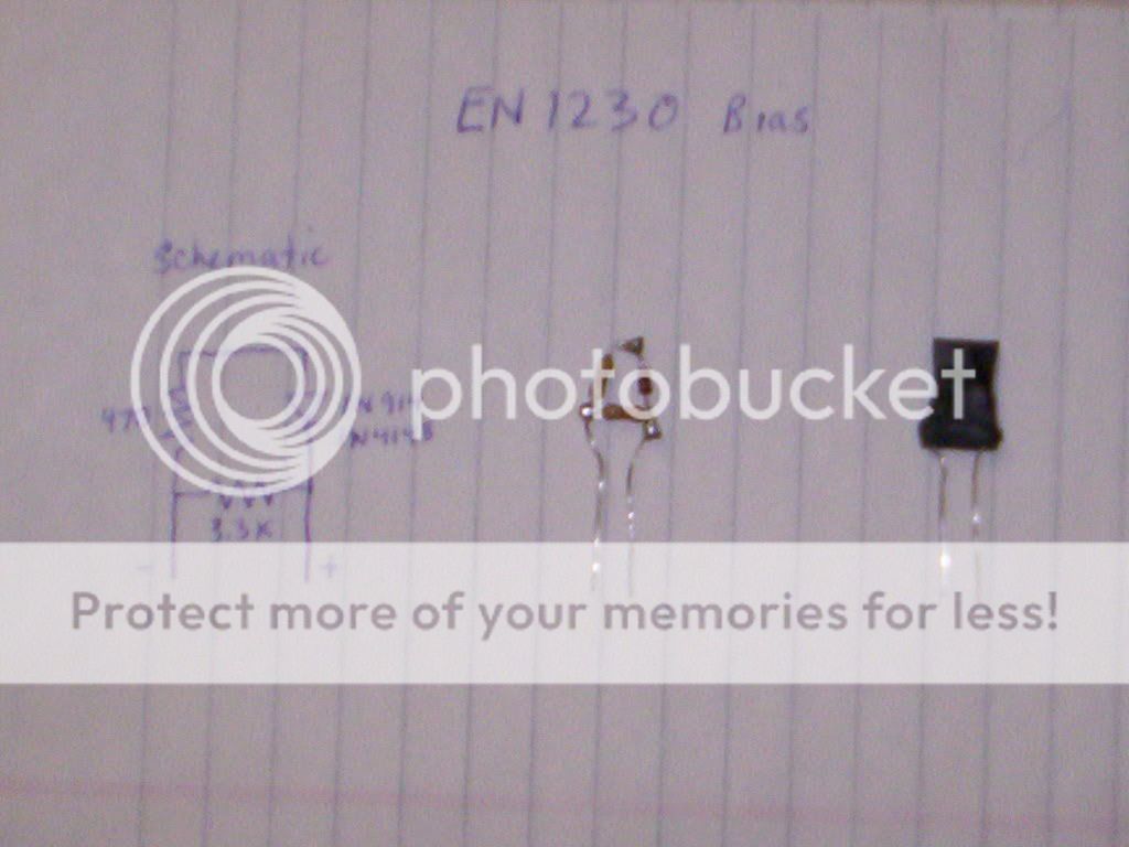
3: change the electrolytic capacitor by the audio IC (C42, 1000uf) to a
3300uf, 16v.
4: Take a turn off the output tuning coil (see tuning coil note below)
5: Remove the AMC potentionmeter (VR4), and put a 1K resistor in it's place.
(only two connections are used on this pot, use those two connections
for the resistor)
6: add a 1K in series with D11.
7: Change R48 to a 33K ohm resistor.
8: Change R55 to a 10K 1 watt resistor.
9: change C37, and C68 to a .2 monolythic (this changes the A.F.
response on TX)
10: Now align the radio, start with the output coil, the the predriver
stage for peak output.
11: Tuning notes: Tune L17 for max with audio. Then, tune L23 for max output with audio, this will upset the radio's frequency. So, after L23 is set, adjust L24 to put the radio back on frequency.
Tuning coil note: If the radio says "made in China" on the back, you must remove 1 turn from the output tuning coil with the slug in it. If it doesn't then you may or may not have to. Count the turns, if it has 4, leave it alone, if it has 5, it's too many and won't tune, remove a turn. You may have to add a 68pf capacitor from the left terminal of the coil to ground, with the solder side of the board up. This method produces better results than just removing the tuning slug.
This mod will consistently produce output between 10-12 watts AVG and 45-50 watts peak. If I can find my video clips of Bird 43P power meter and spec analyzer I took after doing this mod, I'll follow up with those.
Please don't copy and paste this mod to other sites/forums, but feel free to link to it.
Also applies to:
Uniden 78
Cobra 25 & Uniden 76 mod is similar, although you'll need to cross reference against the schematic.
1: change the final to a 2sc1969
2: change the driver to a 2sc2314.
3: change the electrolytic capacitor by the audio IC (C42, 1000uf) to a
3300uf, 16v.
4: Take a turn off the output tuning coil (see tuning coil note below)
5: Remove the AMC potentionmeter (VR4), and put a 1K resistor in it's place.
(only two connections are used on this pot, use those two connections
for the resistor)
6: add a 1K in series with D11.
7: Change R48 to a 33K ohm resistor.
8: Change R55 to a 10K 1 watt resistor.
9: change C37, and C68 to a .2 monolythic (this changes the A.F.
response on TX)
10: Now align the radio, start with the output coil, the the predriver
stage for peak output.
11: Tuning notes: Tune L17 for max with audio. Then, tune L23 for max output with audio, this will upset the radio's frequency. So, after L23 is set, adjust L24 to put the radio back on frequency.
Tuning coil note: If the radio says "made in China" on the back, you must remove 1 turn from the output tuning coil with the slug in it. If it doesn't then you may or may not have to. Count the turns, if it has 4, leave it alone, if it has 5, it's too many and won't tune, remove a turn. You may have to add a 68pf capacitor from the left terminal of the coil to ground, with the solder side of the board up. This method produces better results than just removing the tuning slug.
This mod will consistently produce output between 10-12 watts AVG and 45-50 watts peak. If I can find my video clips of Bird 43P power meter and spec analyzer I took after doing this mod, I'll follow up with those.