• You can now help support WorldwideDX when you shop on Amazon at no additional cost to you! Simply follow this Shop on Amazon link first and a portion of any purchase is sent to WorldwideDX to help with site costs.

Cobra 29 LTD Classic NO RX/TX HELP!!!!!!!!!!!!!

Can you tell me more about the operation of the radio?

You said your wife was talking and you couldn't hear her very well or even have any meter movement...

That can mean a failed part in the RX chain - or out of tune can...or even a switch in the Wrong Position.

Set you radio...
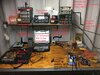
View attachment 35871
You have an LTD - but the above is pretty much the Same panel...

Starting from the LEFT

Set S/RF / SWR / CAL - to S/RF
Set NB / ANL / ANL / OFF - set to OFF
Set CB / PA to CB
Tone (if you have one) To Hi - helps with hearing hiss for RX noise level
Set BRT / DIM to your preference Bright or Dim

RX/TX light - Green for RX, RED on TX...

ANT - Glows RED when you have poor antenna connection or problems with your antenna.

Squelch - Full Counter Clock wise - OFF

Dynamike - Up Clock Wise - ON

RF Gain to MAX

Delta Tune to CENTER (you may be able to feel a detent)
The Radio has a Delta Tune control - it controls the RX FREQUENCY of what you hear as stations tuned into your Receive Frequency - on the channel.

SWR CAL used to CALIBRATE your antennas' POWER for tuning your antenna - you compare Power going to the antenna Forward - against Power Not being Used by the Antenna and is being returned to the Radio (REFLECTED) - this is a ratio - a number - a performance indication of how well your system can be tuned to perform.

Ok, my main concern?
Delta Tune...

In the older days, most radios used Crystal Synthesis - a bank of Crystals that were "mixed" with another bank and when placed thru a tight filter, gave you 23 channels. Now we have 40 but there are still radios out there that are "Fixed" in frequency but slightly off to another radio - you don't hear the differences much, but they can sound distorted. This can happen if you use this radio to talk to another that isn't tuned to your frequency you're receiving. Yes, they are on the same channel, but not the EXACT frequency in the channel band plan.
  • - are you checking the operation of the Delta Tune?
  • - there is a can "L23" which handles IF fro RX, as well as "L24" - being the main tuning coil for the 10.240 Xtal - the true Heart beater (a Required function) of the radio.
If L23 or :L24 were off, or you didn't try tuning in your wife using the Delta Tune control - this may be part of the distortion you're hearing. The radio is just not lined up to hear her correctly - only we have to figure out if it's L23, L24 or Both?

Check also - the operation of the RF gain control - it has to be fully on - turned fully Clockwise to make the receive have it's highest gain so you can hear distant stations.

Ok, I'm going to stop here and let you play with your radio a little bit I want to know what it is you're dealing with when it comes to not being right...

Mark can L23 & L24 ( for reference )
have her transmit and slightly adjust each and see if I can get her cleared up?

would it help if I used a frequency counter?
I don’t have one right now but thinking about getting one soon

IDEA!
Better yet I have a DX55HP which has a clarifier and a +10Khz switch with frequency counter in my truck... this radio pretty much and catch all frequency’s between channels... i can transmit, turn the clarifier until I find what frequency the 29 I’m working on is receiving at... then adjust L23/24 that way u know which direction to go as well .... would that work?
 
You just need a Dummy load in which to use for one of the radios to transmit into - so you can retrieve a signal from it to tune and peak the receiver of the other.

Once that is accomplished, the "TX to RX alignments when it comes to power balance - will be much easier to do.
 
You just need a Dummy load in which to use for one of the radios to transmit into - so you can retrieve a signal from it to tune and peak the receiver of the other.

Once that is accomplished, the "TX to RX alignments when it comes to power balance - will be much easier to do.

I’m confused... so it’s not a good idea to see what frequency the receive is tuned at and put it on channel???
 
UPDATE!
just figured out NB/ANL off is the only time i have RX!!!!

when i did the alignment procedure it had me turn NB/ANL off
 
Ok, slow down, had several replies here, so I'll work with you in the steps I found them...

Had to come back to this to tidy it up a little to help with the flow and hope solve some confusion...

I’m confused... so it’s not a good idea to see what frequency the receive is tuned at and put it on channel???
You'll need one radio - your good one the 55 - to transmit a signal so the other one can hear it. You just need to see if L23 and L24 are too far off the "Channel" both radios are tuned to - say Channel 9 - you should be able to hear the carrier of the 55 - then Tune using Delta Tune to check to see if you can find it's "Center" - you adjust L24 to help with that.
  • Stock Cobra 29 has only L24 to work RX frequency SHIFT, so you only need to adjust L24 to do this.
  • However, L23 can aid in the "centering" of L24 - you need to remember where L23 was originally tuned (Or turned) to and reset it back to that - thru the use of your smartphone to document the process so you can return the L23 back to it's original position.
  • L23 - PEAKS a signal the Receiver uses - so when you adjust L23 - you affect the RECEIVER's ability to HEAR weaker signals. Don't overdo this.
There are other Coil cans that can apply signal to help you with Receive...

L18...
  • A PEAKNIG coil to send 16MHz from the Radios' Carrier Oscillator (L19 included for TX side) to FET1 for RX.
  • The signal is mixed at FET1 and generates the new Intermediate Frequency that the radio can amplify to a better degree with filtering to reduce noise and improve gain.
  • This function takes L18's signal (as a Carrier Signal) the PLL tracks - and SUBTRACTS it from 27MHz
  • This generates another signal your 1st IF - or 10.7MHz
  • This new signal is sent thru a Band Pass Filter stage that functions as a PRE-SELECTOR where...
    • IF is sampled and amplified for Noise Blanker to process the signal.
    • In the Noise Blanker circuit, the signal is amplified and PEAKED using a coil L1 to help identify Spikes and Ambient Noise impulses the IF signal can contain.
    • The Amplified signal is then re-applied to the IF frequency INVERTED which then Cancels out much of this Impulse and Spike noises present but allow the IF to pass thru MISSING these sources of noise.
At the Same Time...
  • The IF signal is passing thru this Band Pass Filter and this INCLUDES a 10.7MHz Xtal filter to Sharply narrow down the signal.
  • Once passed thru L4 and L5, if the Operator has chosen to use the NB (Noise Blanker) - the signal that is has developed thru processing is injected together - just past L5 before IF Xtal filter
    • but as an inverted (inverse or upside down mirror image) signal designed to Cancel out the Impulse and spike noise present and embedded in the IF signal you tuned the 27MHz channel to
  • - The Channel selection is accomplished by what the PLL has selected using the 16MHz signal it controls.
  • The Selective filter then provides a narrowed IF signal that contains the 27MHz image - only filtered and mixed down to the channel you selected - the PLL generated an MIXING signal of 16 MHz to remove the 27MHz and generate the Image at 10.7MHz to be further processed.
  • The Noise Blanker then took the Impulse and Spike noises it can process, then applied it Inverted to remove or cancel them out from the IF signal.
Here's a pic of the area I'm referring to above...
Cobra29RXside.png

L23's Purpose In Life is Simple
With everything added in,
it is designed to take away that which you don't need

L23 Peaks IF signal for the Radio to Mix with the 10.7MHz IF - it SUBTRACTS 10.240MHz from the 10.7MHz leaving 455kHz for the 2nd IF.

A Few Words About CAUTION:

To help Balance the Receivers' Gain between stages, a Trimmer Potentiometer is provide to help offset marginal differences between the 1st IF gain levels that can affect how the 2nd IF stage can process the signal.

That Trimmer Is Your Caution - affects gain and Noise level.
If not adjusted properly can make more problems with poor Receiver Performance.
  • The 455kHz signal is sent thru another Crystal filter,
  • then amplified thru a high gain stage of 3 transistors and two peaking Coils one on the Input the other on Output.
After all is said and done with the RF converted to an Image for IF amplification in two stages of mixing - the Output signal can be put thru a Detector and amplified - this is your Audio Frequency a RESULT of Detected Audio Envelope and Carrier it was sent with - and now the radio can take this signal and parse it down to adjust gain for Receiver performance and SELECTIVITY improvements - a factor called AGC or Automatic Gain Control .

Ok, RX description is done for now...we have to use what we learned to get TX side back on track and working properly.

So with you using the Galaxy 55 as a means to transmit a healthy carrier signal so the 29 can receive it...
You adjust L23, L24 and L18 to help peak out L2 - L3 and L4 - L5 - L6 onto L7, L8 and L9...
  • - work carefully and remember L18 affects the L2, L3 and L4
  • - while L24 not only affects TX frequency but the Radios IF frequency at L5, L6 and L7
  • - with 455kHz from that mixing of 10.7 and 10.240 = 455 - at L8 and L9 into the Detector.

Then turn the tables, let the 29' Transmit into the 55 - keep the 55 in RX mode center slot on it's own - and ADJUST L23 to "center" it's carrier into the 55...

Now, if the 29 won't transmit so the 55 can hear it - then we know we have a Bad parts or two, Driver and or Final

We just want the RX side to "line up" then we focus on the TX side and if you have NOT got the radio to produce any carrier, it's is becoming clearer that there is a problem with the TX side and possibly the Final and Driver are out or you have a broken solder joint (possibly more) and it's unable to send out any signal
 
Last edited:
Ok, for the next one... Noise Blanker - it works in one of the first stages of IF sections the Radio uses

  • - in an area they call the PRE-SELECTOR
  • - that what it is , as called by it's by name
    • - it helps the radio narrow down all those signals and amplifies the ones closest to the channels
    • - The Noise blanker is a process of sampling the signals
    • - finding an average value, and then COMPARING it to find the "Spikes" and other unwanted "artifacts" and then amplify the differences and apply this difference inversely - inverted, which cancels out - these noises letting only the RF signal you want, pass thru.
Review this - you have the manuals too - this may help you understand...
LOOK FOR THE CAUTION ARROW
Cobra29RX Strip.jpg
Did you find the CAUTION yet? That area is a Trimmer pot that controls the GAIN of a stage. If it's not set right the whole mess does NOT work very well. If not already done so, set this control to MID-POINT and see if the Receiver recovers better.

The Noise Blanker and ANL work well for SILENCING a speaker from any air noise on a quiet channel - so make sure you have your RF GAIN control sent to MAX - so you can hear weak signals.
Look above at the RX strip and the Arrows, this may help guide you to find out what is going on, The radio just may be out of tune so review the above and work accordingly.
 
Last edited:
This is rework - so you know...

Don't worry, I'm only gently yelling at myself...​

Well, not completely rework...(maybe)

L23 affects RX and TX - because it's the Main IF mix BOTH sides (RX and TX) use...it's the 10.240 PLL main clock. So it looks to L24's output for the IF.

You "tune" L24 - which is another part of the Radios IF processing, it's 10.240MHz.

The Radio already generates a 10.7 IF signal by subtracting what L18 does...so L23 just peaks out what Delta Tune generates, as a varying correction signal you control - against the main 10.240MHz crystal and L24 as a TUNED Circuit the PLL sees for it's main clock frequency to compare everything else to - from L22 and L19 and L18 thru and over to L23....

L24 ALSO is used (indirectly but thru L23) to develop 455kHz or the LAST IF (Final IF)...thru the "Delta tune" knob. It beats against the 10.7MHz IF signal - subtracts from it - and leaves 455kHz for L7 (Originates at), L8 and L9 amplifies for the Detector and AF section to use...

Ok, Got IT? Don't worry if you didn't, it's a lot to think about - take your time - let's get back to our radio...

There are RX frequencies which the Radio uses to DECODE the CB frequencies and process them in higher and higher levels of gain and filtering without the complexity of large parts counts and complex circuit designs...

The next step is L18, it's your TP5 and your 16MHz to 17MHz signal - so once you know how L23 and L24 work, you'll see where L18 PEAKS the performance of RX side but only in the first stages of IF and RF amplification.

L22 is for L19 and L18 - but L22 is exclusive to the PLL and functions a loop oscillator to provide L19 and L18 signals - but it SAMPLES them to make sure they are what the Channel SELECTOR says they should be.
  • To track this, the PLL lets' L22 run, but in the process of running, it needs a method of tuning resonance to make the L22 coil even oscillate - so it sees capacitance added as a means to make it resonate. This generates the oscillation "ring".
  • To capture that energy, a special Mixer chip - AMPLIFIES this effect and reapplies it back into the loop - keeping the oscillation going.
    • The Chip also BUFFERS the oscillation so the L19 and L18 can see the oscillator action so they can peak their response to and allow power to be branched off of them for the radio to process.
  • The PLL samples this "Ring and Oscillation" and adjusts - tracks this event and adjusts the oscillator thru a VARACTOR.
  • - L22 sees the Varactor as a capacitor
  • - but the PLL uses the ability of the Varactor to change it's capacitance by sending it a small change in voltage being applied to this Diode.
Varactor.jpg
  • The PLL sends the Varactor this "error correction" signal and then continues to sample the loop and this process allows the PLL to take control of the Loop and the Oscillation - this process is called a "LOCK" - which is the ability for the PLL to control L22 as a Local Oscillator and keep the timing correct to make the proper IF signals to let the Radio change the Channels and provide Receive and Transmit is one package.
L23 - affects 2nd IF as well as the TX sections other half of signal L19 uses to make 27MHz...
L24 is the main Clock 10.240MHz - that both the PLL and Delta - Tune for your RX use.
The PLL also uses this Main Clock (L24) for timing AND tracking of it's own Loop at L22 and L19 - for TX but PEAKS L18 for use with Image for 10.7MHz IF Production (your 1st IF stage)

The PLL generates another signal that L19 and L18 use. But there is an important step the PLL does to change what L19's Signal does, and this affects L18's ability to provide a means to SUBTRACT a frequency it supplies to the 1st IF stage - so you obtain a 10.7MHz IF signal to process thru a stage that amplifies your Received CB signal, converts it thru a process of mixing - DOWN to 10.7MHz.

Remember - we have 455kHz signal that is the Subtracted Image from 10.7MHz and the 10.240 Carrier signal the radio beats with, or mixes with - it the result of the 10.7 Downmix to make the 455kHz Image you hear for Receive, we don't need it - nor use it - for TX side...

So the PLL SHIFTS it's frequency and uses L19 and L23 together to Mix and combine to form a 27MHz carrier for the Pre-driver to use and sends that to the Driver and Final for transmitter output.

But what about L22?
L22 is the PLLs own oscillator that it runs and lets L19 and L18 look to, for sync with and provide peaking for amplified output the Loop provides the base 16 to 17MHz signal - only L22 is controlled by the PLL and so when you TX or RX - depending on the mode - the radio shifts its L22 frequency Up or Down 455kHz and the proper coils L18 or L!9 are used to generate, peak and select the channel frequency - the IF signals DERIVED from this mixing - is what carrier signals the radio uses to make the Images form in your Receiver to obtain the RF signals present of the channel you select.

This mixing stuff is not complicated, but then understandably the thought process to figure this out - it's how they have to make it work - is what makes this so confusing.- the routing nightmare...

The Process is called Hererodyne - you mix two signals together - you get 3 products - thru a process of Addition, Subtraction to your Original signal - you can attain an "Image" of the Original - but at a different frequency that is above and below your ORIGINAL one...

Heterodyne.jpg
This is a big post, so I'll have to let you read thru this and I hope it helps you understand the Radios Receive and Transmit and the Mixing process to make the two modes work.
 
Last edited:
This is rework - so you know...

Don't worry, I'm only gently yelling at myself...​

Well, not completely rework...(maybe)

L23 affects RX and TX - because it's the Main IF mix BOTH sides (RX and TX) use...it's the 10.240 PLL main clock. So it looks to L24's output for the IF.

You "tune" L24 - which is another part of the Radios IF processing, it's 10.240MHz.

The Radio already generates a 10.7 IF signal by subtracting what L18 does...so L23 just peaks out what Delta Tune generates, as a varying correction signal you control - against the main 10.240MHz crystal and L24 as a TUNED Circuit the PLL sees for it's main clock frequency to compare everything else to - from L22 and L19 and L18 thru and over to L23....

L24 ALSO is used (indirectly but thru L23) to develop 455kHz or the LAST IF (Final IF)...thru the "Delta tune" knob. It beats against the 10.7MHz IF signal - subtracts from it - and leaves 455kHz for L7 (Originates at), L8 and L9 amplifies for the Detector and AF section to use...

Ok, Got IT? Don't worry if you didn't, it's a lot to think about - take your time - let's get back to our radio...

There are RX frequencies which the Radio uses to DECODE the CB frequencies and process them in higher and higher levels of gain and filtering without the complexity of large parts counts and complex circuit designs...

The next step is L18, it's your TP5 and your 16MHz to 17MHz signal - so once you know how L23 and L24 work, you'll see where L18 PEAKS the performance of RX side but only in the first stages of IF and RF amplification.

L22 is for L19 and L18 - but L22 is exclusive to the PLL and functions a loop oscillator to provide L19 and L18 signals - but it SAMPLES them to make sure they are what the Channel SELECTOR says they should be.
  • To track this, the PLL lets' L22 run, but in the process of running, it needs a method of tuning resonance to make the L22 coil even oscillate - so it sees capacitance added as a means to make it resonate. This generates the oscillation "ring".
  • To capture that energy, a special Mixer chip - AMPLIFIES this effect and reapplies it back into the loop - keeping the oscillation going.
    • The Chip also BUFFERS the oscillation so the L19 and L18 can see the oscillator action so they can peak their response to and allow power to be branched off of them for the radio to process.
  • The PLL samples this "Ring and Oscillation" and adjusts - tracks this event and adjusts the oscillator thru a VARACTOR.
  • - L22 sees the Varactor as a capacitor
  • - but the PLL uses the ability of the Varactor to change it's capacitance by sending it a small change in voltage being applied to this Diode.
  • The PLL sends the Varactor this "error correction" signal and then continues to sample the loop and this process allows the PLL to take control of the Loop and the Oscillation - this process is called a "LOCK" - which is the ability for the PLL to control L22 as a Local Oscillator and keep the timing correct to make the proper IF signals to let the Radio change the Channels and provide Receive and Transmit is one package.
L23 - affects 2nd IF as well as the TX sections other half of signal L19 uses to make 27MHz...
L24 is the main Clock 10.240MHz - that both the PLL and Delta - Tune for your RX use.
The PLL also uses this Main Clock (L24) for timing AND tracking of it's own Loop at L22 and L19 - for TX but PEAKS L18 for use with Image for 10.7MHz IF Production (your 1st IF stage)

The PLL generates another signal that L19 and L18 use. But there is an important step the PLL does to change what L19's Signal does, and this affects L18's ability to provide a means to SUBTRACT a frequency it supplies to the 1st IF stage - so you obtain a 10.7MHz IF signal to process thru a stage that amplifies your Received CB signal, converts it thru a process of mixing - DOWN to 10.7MHz.

Remember - we have 455kHz signal that is the Subtracted Image from 10.7MHz and the 10.240 Carrier signal the radio beats with, or mixes with - it the result of the 10.7 Downmix to make the 455kHz Image you hear for Receive, we don't need it - nor use it - for TX side...

So the PLL SHIFTS it's frequency and uses L19 and L23 together to Mix and combine to form a 27MHz carrier for the Pre-driver to use and sends that to the Driver and Final for transmitter output.

But what about L22?
L22 is the PLLs own oscillator that it runs and lets L19 and L18 look to, for sync with and provide peaking for amplified output the Loop provides the base 16 to 17MHz signal - only L22 is controlled by the PLL and so when you TX or RX - depending on the mode - the radio shifts its L22 frequency Up or Down 455kHz and the proper coils L18 or L!9 are used to generate, peak and select the channel frequency - the IF signals DERIVED from this mixing - is what carrier signals the radio uses to make the Images form in your Receiver to obtain the RF signals present of the channel you select.

This mixing stuff is not complicated, but then understandably the thought process to figure this out - it's how they have to make it work - is what makes this so confusing.- the routing nightmare...

The Process is called Hererodyne - you mix two signals together - you get 3 products - thru a process of Addition, Subtraction to your Original signal - you can attain an "Image" of the Original - but at a different frequency that is above and below your ORIGINAL one...
This is a big post, so I'll have to let you read thru this and I hope it helps you understand the Radios Receive and Transmit and the Mixing process to make the two modes work.


All I have to say is WOW I can’t even begin to express my appreciation for all your work getting this information to me... the best thing I can to show my gratitude is learn all that I possibly can and keep the radio technician hobby going!

best part is... I have full receive! With NB/ANL on I have receive as I should... it may be a little off but I will get to a full alignment when I get a frequency counter probe type...

Kind of funny story actually, I was opening a box I received in the mail I purchased 2 RM Italy stinger boards to put in other radios and I kicked on my base station radio just to hear some chatter on channel 6 and it was almost constant transmission with all the people skipping and running big amps... so I said huh flipped it on over to my unit I’m working on... started adjusting L24... a little more than the other day. Then POOF like a magic show I had a clearer receive! So I got my son in my wife’s truck to radio check my direction and fine tuned it for best receive... I turned off ANL/NB and the receive was working properly perfect crystal clear...


I’m going to sit down and go through your description of operation later with a printed block diagram so I can better grasp the circuitry process and use the diagram side by side to follow along...


We just need now to work on TX! I still have to dead key no carrier... the final has been replaced with known good one... I have not tested the driver ... first driver...? If that’s what it’s called... I do have a component tester I can insert a component into transistor resistor caps diodes etc. and it will display values and let me know if that Component is bad... I do have a multi meter and I can test diodes caps and resistors but installing them in this tester and pressing test seems to be super quick and easy


I need to get on the TX circuitry trail and get that figured out


I think the problem with playing around at L23 & L24 Was I don’t think I turned the tuning slug enough... I was going max 3/4 turn then putting back where it was then going other direction putting back where it was I didn’t venture to far from there but once I did get a little further BOOM there it was found it tuned it to clearest I could with a radio that I’m hoping is mostly on channel...

So next on shack equipment is :

Frequency counter (probe type) so I can probe and follow frequencies before and after they are mixed (correct???)

Oscilloscope once I get it Tx I can tune the modulation side... wave form, peak modulation exc.

I may post some pics of what I’ve got and you can refer me from there what else I may need for a full alignment of a radio

THANKS ANDY!


Signal generator was also on the list...

along with RF sampler to hook scope up
 
Thanks for the Flowers, but it still doesn't produce any TX stuff...

So let's look further and see if you have a section that's bad, or you just need a good tuneup...

Ok, now to help with TX - you get a Red light so you many need to "proble a bit, but look this over first so it can help you find the spot that could be bad...

For this...
...Install an External Power Meter and jumper cable to connect it and use a DUMMY LOAD on the METERS' ANTENNA jack to keep the Final blowing...

upload_2020-4-3_9-8-57.png

Don't have a Dummy Load?

  • Make one!
  • PL-259
  • 3 - 150 ohm ( Brown - Green - Brown ) CARBON COMPOSITION (not Wirewound) resistors
  • Twist / Bundle Resistors in parallel
  • solder one "Bundled" end to INSIDE stem of PL-259
  • Solder other "Bundled" end to OUTER Shield of PL-259
upload_2020-4-3_9-14-31.png
Does not need to be High Quality - just Soldered correctly.
Welcome to OHMs - Law...
  • 3 150 ohms resistors is PARALEL work like one resistor
  • - since they are all the same value
    • - that power load is shared amongst the 3 in equal amounts -
  • To simplify this - 150 / 3 = 50 ohms - your perfect 6 - watt dummy load...

In the above SWR meter pic, there is a 15 watt Dummy load from old Radio Shack days - you just need something to keep 50 ohms impedance while you tune the radio by looking at an external SWR /Power meter


I'll continue in another post...
 
Ok, had to put that in there so you can make your own stuff separately - refer to that post.

This one is done so I can help you with something that can get complex - using a separate post...

Ok, without too much detail...

L23 and L24 also provide 1/2 of a signal to the TX side too...

But the other HALF of that signal is where L19 comes into play...

So, for overview,
  • L24 is PLL's main clock and system timing - adjusting L24 adjusts EVERYTHING timing wise...
    • MEANING - NO PEAKING - DOES AFFECT RX and TX FREQUENCY
  • L23 is IF for 2nd IF 10.240 Down mix of 10.7MHz to 455kHz
  • L19 is PLL's TX frequency to be mixed with L23's at IC3
  • IC3 power Mixer and uses L21 as a Bandwidth Peaking filter
    • L21 is a DUAL coil and both coils peak TX frequency to CB band
    • IC3 sends this new mixed 27MHz signal to L20
    • L20 then Peaks for Predriver and sends it into L17 for Driver to process...
  • L17 is PREDRIVER's input signal to be amplified - forms weak carrier.
  • Driver (Behind Heat Sink Panel - Mounted to it) Amplifies Carrier from Predriver and adds in Audio and Bias from REACTANCE MODULATOR - as Collector (Plate) Modulation.
  • Final Amplifies Driver Signal output further and uses Same Collector (Plate) Modulation and sends it to Tank Circuit that L14 Peaks and then to output network and Antenna connector

Let's get back to that one picture with all the diagrams and flowcharting and see if that can help guide you further...

I've added more to it...It's complex, but you only need to know L23 and L19 and L21 work with IC 3 - see below...
Cobra29IFrouting.jpg
Study that for a moment - this is where all the INTERMEDIATE frequencies of the Radio begin (Originate), get Generated, Mixed and or go to be processed

Look For VR 4 and VR 5 they handle some stuff back there by the Big Transformer your Reactance Modulator - if you don't SEE RF on your internal meter - this VR pot (VR5) may be turned the wrong way.

L19 is output of PLL to TX, start peaking that...
Then Look at L21 for Tweaking it - Both coils affect the other so be careful...
  • Know too, that L21 is BANDPASS so one coil tends to work a group of channels on one side of the band - while the other coil in L21 tends to work the opposite side of the band - together you make an AVERAGE Peak response of power across them - they go into L20 for the Pre-driver to work with.
Cobra292078.jpg
Work in Increments...Rome wasn't built in a day....

Install Dummy Load and Power Meter
- set it properly for Power in Low-wattage range
- with Dummy load on Antenna jack of the Meter
- and Coax Cable hooked up to radio and Meter properly

Use Properly Wired Microphone
Set Up Monitor Radio on Same Channel As Radio Under Test
TX RADIO INTO Meter/Dummy Load and only for short moments to check and adjust slugs to verify RF Power is building and continue doing this as you peak out the system - also LISTEN FOR CARRIER ON MONITOR Radio
If you have not already done so - get one of these tools - a CERAMIC Tip Slotted Tool...like this...

upload_2020-4-3_14-39-57.png
It's Handy...
Allows for Smooth Retuning of IF cans...
Won't Stick To Most Dental Work.
  • Starting on Yellow Coil of L21 - slowly turn the full length of the bobbin to find meter movement and show RF power
  • Increment other Coil Bobbin and re-do step above to see if RF power can build
    • Are you Listening?
    • Are You Watching Meter?
  • Tweak L17 and L19 - L20 together as you Look for Wattage to move the needle
  • Work In Small steps
    • Move Slugs Slowly
  • Work Along TX Strip of L20 (Predriver), L17 (Driver) and L21 (Balancer)
  • Unkey Microphone - Check for Heat - Rest yourself too
  • Repeat As Needed
upload_2020-4-3_10-42-18.png
"...Small Moves..." - Contact​
Pretty soon, you'll be making your own Contacts
 
Last edited:
Just a quick upload of what I have in the shack and that’s all for tonight but by the weekends end we will have TX
 

Attachments

  • 1611EC6D-2D97-42AB-B178-B57681D0300D.jpeg
    1611EC6D-2D97-42AB-B178-B57681D0300D.jpeg
    2.1 MB · Views: 17
  • 53A6FB3D-13DB-4DC1-84C2-47B21D40BEE9.jpeg
    53A6FB3D-13DB-4DC1-84C2-47B21D40BEE9.jpeg
    2.2 MB · Views: 16
Hmm. You've got a great head start - don't stop now!

You know you can make $$$ with those tools!
:)

(... And I don't think anyone has ever done up a Tuning manual for the 29 like this... I hope it helps!)
 
Last edited:
Just a description of what I have... it ain’t nothing but a good start... the auto antenna tuner has a dummy load as well as my MJF 300 watt
 

Attachments

  • AC0144A9-2901-43EC-9647-25C2CA35A2D2.jpeg
    AC0144A9-2901-43EC-9647-25C2CA35A2D2.jpeg
    780.4 KB · Views: 7

dxChat
Help Users
  • No one is chatting at the moment.
  • @ Wildcat27:
    Hello I have a old school 2950 receives great on all modes and transmits great on AM but no transmit on SSB. Does anyone have any idea?
  • @ ButtFuzz:
    Good evening from Sunny Salem! What’s shaking?
  • dxBot:
    63Sprint has left the room.
  • dxBot:
    kennyjames 0151 has left the room.