• You can now help support WorldwideDX when you shop on Amazon at no additional cost to you! Simply follow this Shop on Amazon link first and a portion of any purchase is sent to WorldwideDX to help with site costs.

Cobra 29LTD no TX

Robalo

Well-Known Member
Aug 21, 2006
598
246
53
California
1C64502A-7C95-4941-A0D6-AE0ACDEB6A92.jpeg I just got this radio with tx problem on tr21on collector I do not have voltage on rx on B and E I have 7.8v .mmm.
when i tx the mike on collector tr14 and tr 15 read about 35 volts.
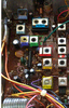
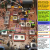
PC-900AC board
 

On TR21 Base and Emitter have 7.8V?

You know the CB / PA switch is where it sources that voltage.

D20 and R101 - head off to MIC Pin 3 - did you check the Pin 3 to see if it has any "residual" voltage present?

So TR21 - as you try to ground Pin 3 MIC to Pin 1 MIC - probe Collector - force Pin 3 low - see if you can get it to click over (Green LED to RED LED) but 35 volts? Looks more like air noise ambient static potentials (no power just static) more like an open line ... or popped resistor.

If it does NOT want to turn RED - but Green goes off, you're ok with the TR21 circuit for now...

Locate Pin 11 on PLL, does it have 5V?

Pin 19 - of PLL - any signal?

Pin 9 is Transmit/Receive "toggle" so it can shift that 455kHz for IF...that is also at Pin 3 on the MIC too. See if this line even changes state...D15's banded end is a good buffer spot to check
 
Last edited:
Locate Pin 11 on PLL, does it have 5V?
yes it does have 4.8 V
Pin 19 - of PLL - any signal?
Yes rx 1.6 V and on TX 2.6 v
Pin 9 is Transmit/Receive
yes RX 4.8v TX 0.67 V
at Pin 3 on the MIC
PIN 3 8.6 V ON RX AND 0.12V ON TX
D15's banded end
RX 8.6 V AND TX 0.28V
get it to click over (Green LED
YES IT DOES
NOOOOOOOOOOOO!
 
I noticed you took out the VCO amp/Mixer
upload_2021-5-29_10-9-40.png

Even the Final and Driver...
upload_2021-5-29_10-10-36.png
(...These are rare ... but if still good, put them back in!...)
(... No wonder why it doesn't TX,...:) - It's part of the problem , you took out the TX side...)

It seem to me, that you really could have left these in, and went after those VCO coils instead...

It's an unfortunate event, but when you have dried out shorted, electrolytic caps, the VCO coils being in line with them as part of the power feed into the oscillator section - usually get taken out or blow open due to the current surges those dried out caps cause.

I'd pull the cans off the coils (leave their body installed on the board) and investigate continuity of the coil winds and see if power can flow thru them - to see if they can work in circuit.
I do know the wax is in there, so work accordingly - if you have to, check for continuity on the bottoms, foil sides, then if they show open, then pull that coils case off and see if a wire is pulled, broken loose from the pin it's supposed to be on.​


In most cases:

When you have NO RED led lit means the PLL is out of lock or not getting the right voltage.

Pin 7 and 11 are those power feeds, Pin 9 verifies the PLL does see the TX and RX stuff

But The VCO will have to fire up, it has to communicate using Pin 19,
  • so check (don't destroy) the 10.240 Xtal circuit, see if you can even get the crystal fired up to feed the PLL. A simple RF probe on the scope to verify - put it on Pin 13 - you should see something.

 
Last edited:
No reading on L22?

See if the PLL is trying to "ring it" by you looking/Scoping at PLL Pin 10 - I'm trying to find out if the PLL is even alive...

IC2, <<-VCO Mixer, if you took that 7310 out of there, time to check L22's path to it, uses C87 to send whatever PLL's Pin 10 "rings" at L22 That 1/2 - 10.240 MHz Clock, that 5.12MHz Signal.
  • IC3 TX Mixer, if there is problems with that, L23 and L20/21 use it...so you get noise on L23...
Back to IC2 Along the way - look for another cap - about 220pF - called C163, that takes some of the signal to ground to help sharpen up the signal - make sure the wax or glue didn't leak into it and ruin it's value.

May have to recheck the winds of L22.- or it's slug see if it cracked.

L21 and L20 use IC3 - so see if those coils can tune or even their condition of the slugs...

L22 is the main ability of PLL to "lock" so if the PLL doesn't lock - TX won't work either.

Usually L22s' slug when positioned is about 2/3rd's to 3/4th's up from the bottom - not flush with the top. Check to see if you can hear IF noise once the PLL locks in. You should hear a noise rise - like regular RX noise from both 10.7 (~16MHz IF Mix) and the 10.240 / 455kHz IF's all sync';d together - means the RX side is aligned.
 
Last edited:
It is good
called C163
it is good
TP 3 give your 1St IF is about 16~17MHz
i have 16.530 mhz
The TP for that is TP1 - when you tune n to CH 40 - you get one voltage - CH 1 is another - and both should be adjustable - on voltage when you tweak L19 / L18
channel 40 3.2 v on tx and rx 2.v
channel 1 2.0 v on tx and rx 1.12 more new parts******* jajaja
 

Attachments

  • 2B0A833E-5914-43E5-AA41-1C62F120B21C.jpeg
    2B0A833E-5914-43E5-AA41-1C62F120B21C.jpeg
    996.1 KB · Views: 10
  • 4CE7A057-F9B6-4F26-A672-0B4D71D7BE52.jpeg
    4CE7A057-F9B6-4F26-A672-0B4D71D7BE52.jpeg
    1.4 MB · Views: 10
  • FA1C33BD-1B49-4C9A-ABCE-16204CE0D15A.jpeg
    FA1C33BD-1B49-4C9A-ABCE-16204CE0D15A.jpeg
    1.1 MB · Views: 10
  • 48EABB38-14CE-4DD2-AC18-426F97C5AD17.jpeg
    48EABB38-14CE-4DD2-AC18-426F97C5AD17.jpeg
    735.7 KB · Views: 10
Ya' solved that problem, @NZ8N - thanks!

L22 - you should have seen 5.12MHz

L18 / L19 - you had ~16MHz - so then, yes, TR21 the TX switch - confirmed by...
now if i inject 8.00 volts to collector of tr 21 i have tx red light good modulation:mad::mad::mad: why c of tr21 do not have voltages

But here's where I went wrong...

This is what threw me off...

I do not have reading on oscilloscope on L22 and L18, L23 work good noise level on and of if a peak the coil,

How come you didn't get any reading from any sort of probing?

Or what parts did you change after the post?

IF the above photos are any indication - it seemed to need a full recap.

There's a part I wanted to point out you don't see this part in this type of package very often anymore - at least they don't use them like they should.
.
It's a throwback to the TTL days of noise abatement - needed to prevent false triggering from shifts and demands of older logic systems doing various arithmetic and or data transfers, a 4 bit Binary "cap" filter to clean up signals on buss lines.

upload_2021-5-31_9-7-6.png

These parts usually don't go out, when Uniden and Cobra went their separate ways, KEPC - they never really went back to putting these back in, yet many makers don't realize how well this, the part, worked, helping keeping a quieter receive and how it helped reducing outside noise from entering into the radio - thru the channel knob.

Although the channel selector was more Octal than Hex, they still subbed in caps to quiet the other limes from the PLL.

upload_2021-5-31_9-20-4.png
 
Last edited:
The uPD2816 and later branded "Cobra29" PLLs use BCD (Binary Coded Decimal) for ROM encoded channel selection, the first 4 pins 1 through 4 are your "Ones" from 0001 (1 decimal) through 1001 (9 decimal), and the next 2 lines are your "Tens", 00 through 11 (30 decimal). Ch40 is all Zeroes on all 6 programming pins.

https://www.radiomods.co.nz/integratedcircuits/upd2814.html

Having capacitors from these pins to Ground does what Andy said above, and also "debounces" the input lines so they don't have odd random codes in between channel click selections, which would cause an "Illegal Code/Out of Lock" condition.
 

dxChat
Help Users
  • No one is chatting at the moment.
  • @ Wildcat27:
    Hello I have a old school 2950 receives great on all modes and transmits great on AM but no transmit on SSB. Does anyone have any idea?
  • @ ButtFuzz:
    Good evening from Sunny Salem! What’s shaking?
  • dxBot:
    63Sprint has left the room.
  • dxBot:
    kennyjames 0151 has left the room.