What is this mod suppose to do? Seen a few radio with itThat's a final/driver - and, if left on too long - radio killer.
Can wreck the radio to beyond its worth to repair.
Seen several with melted transformers and burnt - brittle boards from the heat.
Hopefully this one didn't suffer too much damage.

You are using an out of date browser. It may not display this or other websites correctly.
You should upgrade or use an alternative browser.
You should upgrade or use an alternative browser.
-
You can now help support WorldwideDX when you shop on Amazon at no additional cost to you! Simply follow this Shop on Amazon link first and a portion of any purchase is sent to WorldwideDX to help with site costs.
-
A Winner has been chosen for the 2026 July 4th Retevis RA89R Giveaway! Click Here to see who won!
Cobra 89gtl/ cobra 29 Keeps Blowing finals
- Thread starter BAGEBOY
- Start date
When the Diode is missing, you can get NEGATIVE peaks that will go beyond the 12 volt power the transformer will work with and easily produce - too much back EMF from the modulation swing will damage the Driver and the Final.
Long story...read on...
The Clipper Diode - as they call it, just keeps the POSITIVE voltages into the circuit, it clips or stops the negative going ones that can kill the output transistors from too much negative voltage - being the voltage BELOW ground level the transformer will send out...Puts them in Reverse bias and will destroy them.
There is also a secondary effect of FM-ing - called PHASE modulation, that is added into that Transformers output - which places a LOT of power as an FM Component into the AM envelope - making it sound somewhat "fuzzy" and distorted. Some like this effect, but the radio isn't made for this type of operation.
 Variable on the this radio is a lot like what you already have in line now. R49 is removed, you install the variable there at the holes - locate the driver and the NEGATIVE side goes to the Driver side Hole, the Input side is opposite hole, the power the goes in to the Driver, from the Audio Modulation Transformer.
If you wanted, you can make a fixed Swing - by removing R49 and using a Resistor Cap combo to try various levels of resistor to Capacitor values and listen to the results.
Then you can try to add a variable if you want, but again, a variable is what it is. It varies DC power but keeps audio passing thru it with little reduction - so it can sound distorted when you really swing it with low - carrier power to high power peaks. So that's why I wanted you to try the Resistor cap mod, then SELECT the right capacitor to achieve the effect you want ACROSS the variable range.
- so, once it's in there - to keep everything working - don't short it out - short story...
Long story...read on...
The Clipper Diode - as they call it, just keeps the POSITIVE voltages into the circuit, it clips or stops the negative going ones that can kill the output transistors from too much negative voltage - being the voltage BELOW ground level the transformer will send out...Puts them in Reverse bias and will destroy them.
There is also a secondary effect of FM-ing - called PHASE modulation, that is added into that Transformers output - which places a LOT of power as an FM Component into the AM envelope - making it sound somewhat "fuzzy" and distorted. Some like this effect, but the radio isn't made for this type of operation.
If you wanted, you can make a fixed Swing - by removing R49 and using a Resistor Cap combo to try various levels of resistor to Capacitor values and listen to the results.
Then you can try to add a variable if you want, but again, a variable is what it is. It varies DC power but keeps audio passing thru it with little reduction - so it can sound distorted when you really swing it with low - carrier power to high power peaks. So that's why I wanted you to try the Resistor cap mod, then SELECT the right capacitor to achieve the effect you want ACROSS the variable range.

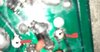
That's is R50 let me take a pic from my scrap and show u. So what value variable I would use if I wanted too ? So would that up to maximum power from 1 or 2 watts key ..I know some when u reduce the key the power drops. I also saw a variable mod by removing s coil and adding 2 wires to a transistor and capacitor and then going to a variable
Attachments
Thnk you, because I was really trying to decipher this...

Trying to figure out how or what angle you took the photo from so I knew where the FRONT of the radio was.
In these, it is to the RIGHT
Trying to figure out how or what angle you took the photo from so I knew where the FRONT of the radio was.
In these, it is to the RIGHT

Schematically, it showing 4.7 OHM 1/2 W - so start kinda in the same ballpark but only higher ohmic values.
Keep a cap handy - say between 22uF to as much as 100uF no more than that. Need to be rated for at least 16V.
The Value of Resistor? Try 18 or 22 ohm underneath and leave the legs in the holes not sohrting to help mount caps a your try to find the right swing and see if it gives you what you want in CARRIER.
For - swing audio? use the CAP on the top side of trhe board for room but make sure the BAND (Black Band Cathode side) points to DRIVER
The Variable? I thought you knew...
There are two - done by yourself or you can look for
https://www.worldwidedx.com/threads/cobra-29-variable-power.261968/
I always use a 5k pot..but from reading ..I don't need to use TIP 120 OR EQUIVALENT? Ii see sait I can use a capacitor At the top and the variable on the solder side..ISchematically, it showing 4.7 OHM 1/2 W - so start kinda in the same ballpark but only higher ohmic values.
Keep a cap handy - say between 22uF to as much as 100uF no more than that. Need to be rated for at least 16V.
The Value of Resistor? Try 18 or 22 ohm underneath and leave the legs in the holes not sohrting to help mount caps a your try to find the right swing and see if it gives you what you want in CARRIER.
For - swing audio? use the CAP on the top side of trhe board for room but make sure the BAND (Black Band Cathode side) points to DRIVER
The Variable? I thought you knew...
There are two - done by yourself or you can look for
https://www.worldwidedx.com/threads/cobra-29-variable-power.261968/
What I wanted you to try is the PROPER value capacitor you'll need so you won't sound distorted when you use the variable.
Have you even tried to see if the fixed values and what you'll sound like BEFORE you install the variable? I think you should - others that hear the results might like it, for if you don't pay attention to details like this - you'll receive laughter instead.
Why does this matter?
Put too much audio into an older Driver in a chassis like that, and with the heat it's been producing?
IT could wind up an EPIC fail.
IN these older radios the 2028/2029 parings - as crippled in power as they were, does heat up because of an intrinsic effect of heavy doping in the junctions of these newer (back then they are modern, today they're relics) die style transistors capable of higher MHz (Maximum Useable Frequency or MUF) bands and a really different design - they made what the 2078 and the 2312/1969 are "standard" of their day, but still are relics when it comes to the junction efficiency (a Siemens/Ohmic impedance result).
So if you put a 100uF cap in there you may blow the Driver - then what? Start all over...
I'm trying to help you do this right so when you get the right effect - you're variable works like it should and not make you a distorted muddy mess you could becomes had you simply used the "Defaults" everyone else wanted you to use.
The potential (SIC) is there - You'll blow the parts that give you the classic sounds you have OEM - but if I'm too late - well, then do what you want but you will have to use the Variable install at R49 - with AGAIN - the NEGATIVE side towards the DRIVER Collector and the Positive side to the opposite hole of R49 - then run your "pot wire" to any convenient spot or your RF gain / Squelch like you wish.
- IF you run too much capacitance - you're letting thru too much audio - causing distortion - BACK off use a lower value - it's why I wanted you to tweak the values before you try the variable - for as you lower your carrier - the audio doesn't go lower too - it STAYS the same - so that signal will get way too loud and even destroy your work.
dxChat
- No one is chatting at the moment.