• You can now help support WorldwideDX when you shop on Amazon at no additional cost to you! Simply follow this Shop on Amazon link first and a portion of any purchase is sent to WorldwideDX to help with site costs.

Cobra XL 450

PAPA

Active Member
Feb 20, 2010
839
0
26
Montans
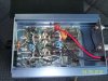
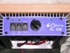
I have a Cobra XL 450 linear,

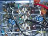
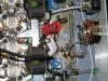
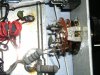
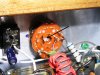
The resistors to the power switch got hot over time and I wanted to replace them.

They were burnt so I cannot tell the band colors on the resistors.

I also removed a few of them already

Can anyone help me out?

Anyone know the values of these resistors?

See images
 

Attachments

  • cobra 001.jpg
    cobra 001.jpg
    1.1 MB · Views: 569
  • cobra 003.jpg
    cobra 003.jpg
    1 MB · Views: 550
  • cobra 005.jpg
    cobra 005.jpg
    1.1 MB · Views: 820

I don't know the original resistor values however, I do know how you can easily restore full power use. Simply connect the center conductor of that RG-174U coax to the ungrounded side of the green 68K capacitor. When reading the cap it will be the left terminal where you removed a resistor. If you do this you may want to reduce your drive level if it sounds distorted on SSB or lacks positive peaks on AM.
 
Anyone have a close up of the power switch so I can see how to re-hook it up LOL

Nope, when I repair these I have to use ohm meter to "ring" out what does what. Depending on what you use the amplifier for I would just do as described above or add a variable power to it using a 2 watt 100 ohm potentiometer and some 2 watt 100 ohm resistors. These amplifiers have a decent class AB bias circuit and do not need a lot of drive. How much carrier and power are you feeding the amplifier with?

To add the variable power pot you would need to feed the center leg of the pot with center conductor of the small coax you pictured that used to go to the rotary switch. One outer leg of the pot would then connect to the input of the amplifier where green cap is (dark brown rosin spot on the board) through a 5 or 10 ohm 2 watt resistor. The other out leg would go to ground through a 100 ohm 2 watt resistor. You may have to swap the outer leads around to your liking as far as which way is up and which way is down.
This will give you variable input power instead a 4 position switch.
Or do like someone else mentioned and feed it directly to where the green cap (I think it is marked 68) and then solder a 100 ohm 2 watt resistor from the point where the green cap is to ground. Lower value resistors like a 50 ohm will give you more attenuation on the input.
 
Thanks for the reply,

See the new image I just uploaded,

The small coax should go where the arrow is pointing?

I got the amp from a guy that was driving it with every radio he had LOL I think it was a Kenwood 440 and A Yaesu 840, so who knows what power he was running, but it looks like it was to high?

I forgot where the little coax center went and where the resistors went, but like I said above, I believe the coax went on the spot where the arrow is pointing???????????

If you want more pictures of a specific area let me know.

I am a little confused as to what green cap you are talking about, I see the one on the board and I have a green cap on the power selector switch as well?


Nope, when I repair these I have to use ohm meter to "ring" out what does what. Depending on what you use the amplifier for I would just do as described above or add a variable power to it using a 2 watt 100 ohm potentiometer and some 2 watt 100 ohm resistors. These amplifiers have a decent class AB bias circuit and do not need a lot of drive. How much carrier and power are you feeding the amplifier with?

To add the variable power pot you would need to feed the center leg of the pot with center conductor of the small coax you pictured that used to go to the rotary switch. One outer leg of the pot would then connect to the input of the amplifier where green cap is (dark brown rosin spot on the board) through a 5 or 10 ohm 2 watt resistor. The other out leg would go to ground through a 100 ohm 2 watt resistor. You may have to swap the outer leads around to your liking as far as which way is up and which way is down.
This will give you variable input power instead a 4 position switch.
Or do like someone else mentioned and feed it directly to where the green cap (I think it is marked 68) and then solder a 100 ohm 2 watt resistor from the point where the green cap is to ground. Lower value resistors like a 50 ohm will give you more attenuation on the input.
 

Attachments

  • COBRA_XL450arrow.JPG
    COBRA_XL450arrow.JPG
    520.2 KB · Views: 366
I was referring to the green cap on the board

Thanks for the reply,

See the new image I just uploaded,

The small coax should go where the arrow is pointing?

I got the amp from a guy that was driving it with every radio he had LOL I think it was a Kenwood 440 and A Yaesu 840, so who knows what power he was running, but it looks like it was to high?

I forgot where the little coax center went and where the resistors went, but like I said above, I believe the coax went on the spot where the arrow is pointing???????????

If you want more pictures of a specific area let me know.

I am a little confused as to what green cap you are talking about, I see the one on the board and I have a green cap on the power selector switch as well?
 
It looks to me like the wire went where you drew the arrow and also a 2 resistors in parallel from there to ground. They look like 68 ohms 2 watt.


cobra_xl_450%20_inside2.jpg
 
I've been through 4 of these amps over the last 5 years or so, along with being good AB amps. I had two versions with the MRF 454s' and two with the 2290s.......although the 454's did slightly more for some reason or other.

Always pretty much the same , 2 to 20 on AM would give me a little over 100 watt DK with slightly over 400 pep and about the same on SSB with the 454's and slightly less with the 2290s.


these are truly a SSB'ers delight. Same maker takes pride in all his boxes over the years , I never saw one of his that wasn't AB , he also made the Blue face Palomar 225's 250's 350's (Also with the Galaxy name on them, also blue) as well as the Palomar/Magnum name on them as well as the Skipper/Palomar name on them and the Cobra XL name. (I think he really likes the color blue) (-:

Wrap around blue heat sinks = 250s , 350s , 450s and 650s (you don't see many of the 650s around) 1 driving 4 with the wrap around heat sink.

He also makes or made a nice Skipper/Pal base unit , you will pretty much see these on Ebay at one time or the other. CB World guy was wrong , not made in Mexico , Washington State would be more like it. (y)
 

dxChat
Help Users
  • No one is chatting at the moment.