I have a connex cx-3300HP that receives fine but does not measure any signal on my s meter. The s meter works fine in transmit. I have proper voltages on IC 1. My RF gain is working. D12 is fine. PIN diodes are fine. This thing has me stumped. Any assistance would be much appreciated....and, yes, all ground wires that go to the pots are good as well.

You are using an out of date browser. It may not display this or other websites correctly.
You should upgrade or use an alternative browser.
You should upgrade or use an alternative browser.
-
You can now help support WorldwideDX when you shop on Amazon at no additional cost to you! Simply follow this Shop on Amazon link first and a portion of any purchase is sent to WorldwideDX to help with site costs.
-
A Winner has been chosen for the 2026 July 4th Retevis RA89R Giveaway! Click Here to see who won!
Connex cx-3300HP Receive S meter issues
- Thread starter Alabama Trainman
- Start date
This is a AM radio. No TR13 or 14. If I remember correctly, TR13 has a jumper and TR14 is unpopulated. I'm seeing the voltage increases with AGC at IC1 but still no meter deflection with a signal generator at the antenna jack.Assuming you have tried adjusting VR1 (AM) and VR2 (SSB) S meter, check for .7v on the base of TR13 in AM mode; .7v on the base of TR14 in SSB mode.
Check C31 & C32; D13 & D14
LOL Apologies. Let me see if I can find a suitable schematic and get back to you.This is a AM radio. No TR13 or 14. If I remember correctly, TR13 has a jumper and TR14 is unpopulated. I'm seeing the voltage increases with AGC at IC1 but still no meter deflection with a signal generator at the antenna jack.
What if you inject a signal farther down the IF chain?
Attachments
I believe this schematic will match your radio or be close to it.
You said that D12 and your PIN diodes (D10 & D11) were ok. Try jumping D11.
Next I would check C32, D8 & D9. Then PIN diodes D23 & D24 and C71.
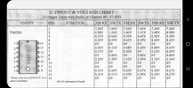
IC1 (quad Op Amp) pins 5, 6, and 7 are 1 of the 4 OP Amps in IC1.
You said that D12 and your PIN diodes (D10 & D11) were ok. Try jumping D11.
Next I would check C32, D8 & D9. Then PIN diodes D23 & D24 and C71.
IC1 (quad Op Amp) pins 5, 6, and 7 are 1 of the 4 OP Amps in IC1.
Attachments
Along with what @Dr_DX has mentioned -

Locate #35 that pin/hole combination goes to a switch AM / FM - even though you say it does not have FM - IF it has 8V all the time in RX and TX then suspect wiring issues to the Front panel or the MODE (AM / PA) is faulty. If this is so, then a steering diode has failed and is holding something quenched (on) that should be off, by your Voltage readings the steering diode condition is more rare but not impossible.
Pin 67 is the S-meter/RF meter out - so if you're getting RF indication on TX - and the Meters' own coil shows good. Then the RX side L6 on thru to the Detector just might need a tweak.
Locate R47 - usually 3.9K resistor - that is the output buffer to the S-Meter along with VR1 - might want to measure across R47 to ground to see if the S meter is getting sent anything.
The RF side shares this line with the R47 - so the resistor just sends S Meter indication from IC1 to the RF Meter line thru that trimmer. (Vr1)
Now, it can be possible that D12 may have survived, R47 and VR1 all check ok - then suspect that IC1 output was damaged...
The 3600-14B boards were notorious for thin tracings and open lines - check continuity of Hole 67 to R47 - I've seen them open due to the current draw the meter will take - may exceed the tracing thickness and open or the Resistor can fail open - breaking the circuit.
Locate #35 that pin/hole combination goes to a switch AM / FM - even though you say it does not have FM - IF it has 8V all the time in RX and TX then suspect wiring issues to the Front panel or the MODE (AM / PA) is faulty. If this is so, then a steering diode has failed and is holding something quenched (on) that should be off, by your Voltage readings the steering diode condition is more rare but not impossible.
Pin 67 is the S-meter/RF meter out - so if you're getting RF indication on TX - and the Meters' own coil shows good. Then the RX side L6 on thru to the Detector just might need a tweak.
Locate R47 - usually 3.9K resistor - that is the output buffer to the S-Meter along with VR1 - might want to measure across R47 to ground to see if the S meter is getting sent anything.
The RF side shares this line with the R47 - so the resistor just sends S Meter indication from IC1 to the RF Meter line thru that trimmer. (Vr1)
Now, it can be possible that D12 may have survived, R47 and VR1 all check ok - then suspect that IC1 output was damaged...
- How? By an RF spike back into the Radio due to an Amp sending a spike back and thru the RF and S Meter line - into R47 and into IC1's S Meter buffer output - blowing that Amp of the Quad Op Amp.
- Not saying it did, but MOSFET and Relayed SSB amps with wildly swinging carriers and PEP issues usually take out IC1 from spikes - the D12 makes the rectified output too high and even can kill C164 the "Averaging" cap that RF uses to smooth out.
The 3600-14B boards were notorious for thin tracings and open lines - check continuity of Hole 67 to R47 - I've seen them open due to the current draw the meter will take - may exceed the tracing thickness and open or the Resistor can fail open - breaking the circuit.
Attachments
Last edited:

Thank you, gentleman. I was trying to find one of those circuit descriptions encompassing IC1 which controls the AGC and S/RF circuit functions leading to the meter movement. What you both supplied should get me thru this.
Well, it doesn't look like I'm getting anywhere with this.
D12 is ok
VR1 is ok
Pin Diodes D10,D11 are ok
Tried jumping D11- nothing happened
C32 was replaced
D8 ok
D9 ok
PIN diodes D23,D24 are ok
Replaced C71
IC1 Replaced
Rx side of L6 is good all the way to the detectors.
I did find a problem with voltages on IC 1 pins 5,6,7 and 12,13,14 with the generator on.
I used a working Connex as a comparison.
Troubled Connex with generator on I have the following voltages on the following pins.
Pin5 116mv
Pin6 118mv
Pin7 .223v
Pin12 .313v
Pin13 .316v
Pin14 .627v
Working Connex with generator on I have the
Following voltages on the following pins.
Pin5 1.053v
Pin6 1.049v
Pin7 2.108v
Pin12 1.644v
Pin13 1.636v
Pin14 3.643v
Like I said radio transmits and receives fine. Meter moves in transmit but NOT in receive, yet I hear fine.
I can use diode check on D12 and I do get s meter deflection, so meter movement is fine..just doesn't show on receive.
Did some resistor readings around IC1.
Found quite a difference in resistance readings compared to the schematic
SCHEMO.........................ACTUAL
R41-100k............................ R41-47K
R42- 100k............................R42-51.7k
R36-100k.............................R36- 72.8k
R37-82k.............................. R37- 67.7k
R38-39k...............................R38- 33k
R39- 220k............................R39- 39.2k
R274-200k...........................R274- 40.2k
All others in that circuit were nominal compared to the schematic. I checked 2 other EPT360014B boards and had the same readings
Last edited:
Yes. I took voltage readings on 3 different EPT360014B boards and all measured their marked value.Were your actual measurements within tolerance of the resistor's marked value?
(Have spotty Internet for the moment - so bear with this)
Found part of the opening of this post never posted)
By your readings - you do not have any signal present on IC1 Pin 5 - which kills the S meter and any AGC help it can provide.
Locate R254...

Do a continuity check from it to Pin 5 of IC1.
You have a Diode in the way - D11 - so Continuity to Banded of D11 from Pin 5 - then recheck continuity from D11 unbanded to Bare lead of R254
Measure DC Voltage on bare lead - if it is the SAME voltage as IC1's Pin 5 - then keep working back from R254 - D10, and D11 work as a voltage Doubler to raise and rectify the signal to IC5 - but the rectification won't occur if R254 is open - you have no signal by your troubled (Connex Radio under Repair) readings - so check continuity too from IC5 - back to D10/D11 then from UNBANDED side of D11 and its junction with D10 Banded end - R254 is next - then after that, two capacitors.
Locate D23 - D24 the AM Detector.

This produces the signal used by R254 thru R35 C29 - but SELECTS the signal to sample because C29 is a DC block - that is why I asked about the 8V all the time - if 8V is present all the time - the AM detector can work, but the SIGNAL from it is quenched to get to the AGC.
The Galaxy series radios then uses R34 C28 to send signal from FM and blocks AM signal from getting to the AGC amp - if wiring is screwed up - this is what you might be dealing with.
Check the front panel for problems - if you're seeing D23 and D24 is 8V all the time.
Supposed to be grounded - so look to see if D24 and D23 are good too...you got receive - but from where?
Found part of the opening of this post never posted)
By your readings - you do not have any signal present on IC1 Pin 5 - which kills the S meter and any AGC help it can provide.
Locate R254...
Do a continuity check from it to Pin 5 of IC1.
You have a Diode in the way - D11 - so Continuity to Banded of D11 from Pin 5 - then recheck continuity from D11 unbanded to Bare lead of R254
Measure DC Voltage on bare lead - if it is the SAME voltage as IC1's Pin 5 - then keep working back from R254 - D10, and D11 work as a voltage Doubler to raise and rectify the signal to IC5 - but the rectification won't occur if R254 is open - you have no signal by your troubled (Connex Radio under Repair) readings - so check continuity too from IC5 - back to D10/D11 then from UNBANDED side of D11 and its junction with D10 Banded end - R254 is next - then after that, two capacitors.
Locate D23 - D24 the AM Detector.
This produces the signal used by R254 thru R35 C29 - but SELECTS the signal to sample because C29 is a DC block - that is why I asked about the 8V all the time - if 8V is present all the time - the AM detector can work, but the SIGNAL from it is quenched to get to the AGC.
The Galaxy series radios then uses R34 C28 to send signal from FM and blocks AM signal from getting to the AGC amp - if wiring is screwed up - this is what you might be dealing with.
Check the front panel for problems - if you're seeing D23 and D24 is 8V all the time.
Supposed to be grounded - so look to see if D24 and D23 are good too...you got receive - but from where?
Last edited:
Hey, Andy. You were saying "By your readings- you do not have any signal on pin5 IC1- Which kills s meter and any AGC " I did post that I have approx. 1v at Pin 5 IC1 but only when I was injecting a S-9 signal into the antenna jack with my generator. In RX (idle) there is no signal. The service manual shows no signal on pin5 IC1.(Have spotty Internet for the moment - so bear with this)
Found part of the opening of this post never posted)
By your readings - you do not have any signal present on IC1 Pin 5 - which kills the S meter and any AGC help it can provide.
Locate R254...
View attachment 61068
Do a continuity check from it to Pin 5 of IC1.
You have a Diode in the way - D11 - so Continuity to Banded of D11 from Pin 5 - then recheck continuity from D11 unbanded to Bare lead of R254
Measure DC Voltage on bare lead - if it is the SAME voltage as IC1's Pin 5 - then keep working back from R254 - D10, and D11 work as a voltage Doubler to raise and rectify the signal to IC5 - but the rectification won't occur if R254 is open - you have no signal by your troubled (Connex Radio under Repair) readings - so check continuity too from IC5 - back to D10/D11 then from UNBANDED side of D11 and its junction with D10 Banded end - R254 is next - then after that, two capacitors.
Locate D23 - D24 the AM Detector.
View attachment 61069
This produces the signal used by R254 thru R35 C29 - but SELECTS the signal to sample because C29 is a DC block - that is why I asked about the 8V all the time - if 8V is present all the time - the AM detector can work, but the SIGNAL from it is quenched to get to the AGC.
The Galaxy series radios then uses R34 C28 to send signal from FM and blocks AM signal from getting to the AGC amp - if wiring is screwed up - this is what you might be dealing with.
Check the front panel for problems - if you're seeing D23 and D24 is 8V all the time.
Supposed to be grounded - so look to see if D24 and D23 are good too...you got receive - but from where?
I did the continuity check from cathode of D11 to Pin 5 and it is good. From anode of D11 to R234 I have continuity as well. Voltage on R254? I have no voltage on R254 to compare to voltage on Pin 5 unless my generator is on. Then I have .9 volts.
Hey, Andy. You were saying "By your readings- you do not have any signal on pin5 IC1- Which kills s meter and any AGC " I did post that I have approx. 1v at Pin 5 IC1 but only when I was injecting a S-9 signal into the antenna jack with my generator. In RX (idle) there is no signal. The service manual shows no signal on pin5 IC1.
I did the continuity check from cathode of D11 to Pin 5 and it is good. From anode of D11 to R234 I have continuity as well. Voltage on R254? I have no voltage on R254 to compare to voltage on Pin 5 unless my generator is on. Then I have .9 volts.
Attachments
dxChat
- No one is chatting at the moment.