So after reviewing measurements, the only things that stand out to me are voltages from IC 1 with a generated S9 signal injected. Nominal voltages obtained from IC1 are what they are supposed to be. Pins 5,6,7 voltages are low compared to 2 other EPT360014B boards under the same test. Also, pins 12, 13, 14 voltages are low compared to the other boards under test with generator on. I have measured all resistors and checked all diodes and cannot see any differences between this troubled board and the other working boards.

You are using an out of date browser. It may not display this or other websites correctly.
You should upgrade or use an alternative browser.
You should upgrade or use an alternative browser.
-
You can now help support WorldwideDX when you shop on Amazon at no additional cost to you! Simply follow this Shop on Amazon link first and a portion of any purchase is sent to WorldwideDX to help with site costs.
-
A Winner has been chosen for the 2026 July 4th Retevis RA89R Giveaway! Click Here to see who won!
Connex cx-3300HP Receive S meter issues
- Thread starter Alabama Trainman
- Start date
I did find a problem with voltages on IC 1 pins 5,6,7 and 12,13,14 with the generator on.
I used a working Connex as a comparison.
Troubled Connex with generator on I have the following voltages on the following pins.
Pin5 116mv
Pin6 118mv
Pin7 .223v
Pin12 .313v
Pin13 .316v
Pin14 .627v
Working Connex with generator on I have the
Following voltages on the following pins.
Pin5 1.053v
Pin6 1.049v
Pin7 2.108v
Pin12 1.644v
Pin13 1.636v
Pin14 3.643v
Ok, this is what led me to believe you do not have any signal on Pin 5 -
The "troubled Connex" - see Pin 5 is in mV reading because the input to the "comparator" on that pin is below 0.35V which is (to itself) no signal - that pin is where R254 and D10/D11 go - that is why on the GOOD receiver you see +1V (or more) VDC - then AGC sees this output to the S-meter and then adjusts the GAIN of the RX side.
So with Pin 5 essentially "open" and Pin 6 Following it - both are being sent a signal too low to track.
Pin 7 is "idle current out" 0.223V - or really the LOWEST signal it can even receive. So the Pin 5 is not seeing enough of a signal - so check those 100K resistors - see if they drifted off (lift a leg to check these) - per @Dr_DX - not in circuit else parallel readings of NFB used in this area will rear its head and skew your readings (which is what they look like - a little low)
The "Working Connex" is showing correct voltages - as per the Service Manual.
Which then leads me to the D24 and D23 - which D23 is sent to the Front Panel - The AM that D24 and D23 is - D23 grounds - which "turns on" the AM side, allowing signal at D24 to detect any signal carrier and sends that to the Pin 5 thru the R35 C28 combo and R254 and then D10/D11 Doubler.
IF D23 can't get grounded - the signal present off of D24 is not enough to start the AGC process - doesn't affect Receiver - but it DOES affect the amount of signal current present to process (DC blocking at C29 - Go measure it for yourself)
So to me the "Why" you're not getting S-meter is because there is no signal present on Pin 5 from R254 - and the area in question...

I've drawn it out for you....
an EPT3600-14B Board follows this routing on ALL their lines
The only other thing that can screw this up is at the ANL NB switch,
again, at the Front Panel...sending 8V to kill RX but YOU HAVE RX...
This is about as much help as I can give...the rest is up to you...
Last edited:

I have voltages on troubled Connex...it's just not enough voltage.Ok, this is what led me to believe you do not have any signal on Pin 5 -
The "troubled Connex" - see Pin 5 is in mV reading because the input to the "comparator" on that pin is below 0.35V which is (to itself) no signal - that pin is where R254 and D10/D11 go - that is why on the GOOD receiver you see +1V (or more) VDC - then AGC sees this output to the S-meter and then adjusts the GAIN of the RX side.
So with Pin 5 essentially "open" and Pin 6 Following it - both are being sent a signal too low to track.
Pin 7 is "idle current out" 0.223V - or really the LOWEST signal it can even receive. So the Pin 5 is not seeing enough of a signal - so check those 100K resistors - see if they drifted off (lift a leg to check these) - per @Dr_DX - not in circuit else parallel readings of NFB used in this area will rear its head and skew your readings (which is what they look like - a little low)
The "Working Connex" is showing correct voltages - as per the Service Manual.
Which then leads me to the D24 and D23 - which D23 is sent to the Front Panel - The AM that D24 and D23 is - D23 grounds - which "turns on" the AM side, allowing signal at D24 to detect any signal carrier and sends that to the Pin 5 thru the R35 C28 combo and R254 and then D10/D11 Doubler.
IF D23 can't get grounded - the signal present off of D24 is not enough to start the AGC process - doesn't affect Receiver - but it DOES affect the amount of signal current present to process (DC blocking at C29 - Go measure it for yourself)
So to me the "Why" you're not getting S-meter is because there is no signal present on Pin 5 from R254 - and the area in question...
View attachment 61076Then; how this works is because it needs an AC signal sent to D10 and D11 to rectify into a DC signal to make the comparator work
I've drawn it out for you....
an EPT3600-14B Board follows this routing on ALL their lines
The only other thing that can screw this up is at the ANL NB switch,
again, at the Front Panel...sending 8V to kill RX but YOU HAVE RX...
This is about as much help as I can give...the rest is up to you...
D6, D7, D8, D10, D11, D12 are reading voltages but those voltages are too low compared to the working units measured. I also have .610v on the outside leg of VR1 on the working unit with a signal injected, yet that voltage is absent on the troubled Connex
Pin 4 shows 9.1v in AM, FM and PA.You said you changed out IC1. Does pin 4 of IC1 show 8.5+v in AM RX? What about FM RX?
SUCCESS!!!!!Pin 4 shows 9.1v in AM, FM and PA.
S9 signal being injected and reading S9 on the meter. I traced it back from Pin 5 IC1 and found C29 defective. Thank you for all your support in fixing this issue.
Attachments
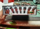
There ya' go!I traced it back from Pin 5 IC1 and found C29 defective
You're welcome...
Thanks to all for their help in this....
dxChat
- No one is chatting at the moment.