Hey Everyone,
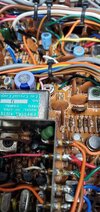
I have a Spartan PLL 40 on the bench for repair and alignment. I have searched hi and low for any info on it. The closest I have found is the Centurion PLL40. I am finding that it is not the same. For instance, in the PLL section the Spartan has 4 CT's and the Centurion has 3 CT's. The radio has issues so I am hoping for a more accurate schematic.


Thanks as always!!!
I have a Spartan PLL 40 on the bench for repair and alignment. I have searched hi and low for any info on it. The closest I have found is the Centurion PLL40. I am finding that it is not the same. For instance, in the PLL section the Spartan has 4 CT's and the Centurion has 3 CT's. The radio has issues so I am hoping for a more accurate schematic.
Thanks as always!!!