D&A Phantom el509/519/6P45C conversion and more
Postby liquidh8 » Wed Jun 27, 2012 12:07 pm
D&A Phantom conversion.
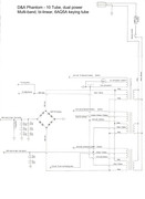
This amp I have is the grey case, 10 tube, dual power, multiband, bi linear, with a 6AQ5A keying tube. Just so we know what I have.
Well, I have posted in a few different threads of other members, but I figured I have gotten far enough to start my own and share my progress thus far. First a bit of background.
Other D&A threads I was posting in:
http://www.worldwidedx.com/home-brew/42092-d-phantom-rework.html
http://www.worldwidedx.com/general-cb-services-discussion/28914-need-part-number-phantom-12-tube-keying-diode.html
http://www.worldwidedx.com/amplifiers/23121-d-pdx-400-a.html
http://www.worldwidedx.com/cb-band-cb-radios/119532-d-phantom-triple-stage-question.html
http://www.worldwidedx.com/amplifiers/115629-d-phantom-12-tube.html
I bought a 10 tube D&A Phantom locally for pretty cheap, even if it didn’t work, I figured the few good tubes and parts were worth more than the price. After getting it home, I went through it with help from the boards, and found a few things wrong. The keying tube (6AQ5A) was bad and 4 of the 6LQ6’s were bad. This amp has dual power, and it had all 6LQ6’s in the drivers and finals. The SSB delay cap exploded on me, and a few of the toggle switches were broke. The BTL (receive amp) seems to work though, as do the transformers and relays.
After looking around and doing some research, like the GLA-1000 conversion, and more outside help, I decided the EL509/519, or in my case, 6P45C conversion would be the cheapest route. I picked up the tubes, and tube sockets. I still need to get all new capacitors for it. I have a good keying tube, though I would like to convert it to transistor keying. I didn’t have an exact schematic for it. So, I took a few of the different D&A schematics, and then just chased wires, and drew my own. The phantom doesn’t seem to have a bias circuit in it, if it sounds crappy on SSB, I would like to add one, but still keep the power levels if possible. I may also add the switch to make it a triple stage.
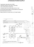
-Proposed Upgrades/fixes would be:
-Bleeding resistors on all the filter caps.
-New heavier duty diodes in the rectifier circuit (1n5408)
-New filter caps with a higher voltage rating, maybe more capacitance, and other electrolytic capacitors.
-Better cooling fans.
-Replace the 302 trimmer caps with 304’s (the original look a bit flakey).
Then see if it works. If it does, which it should
After that, a transistor keying circuit conversion, and maybe a bias circuit.
The amp is kinda rough looking as far as the paint job goes. I don’t mind it much now. I would end up re-doing the RF deck and repainting the whole thing anyway. Moving the BTL switch to the front and changing the tube/transformer layout. I thought about raising the top, since the 6P45C’s are a bit taller. Is there a minimum clearance for the top of the tubes to the case?
Before I get the replies, I know about the sweep tube amps not being transmitting tubes, cost of tubes, yadda yadda. I use this as my nighttime hobby when I only have 1-2 hours a night free here and there. I’ll upgrade to a real transmitting tube amp down the line when I learn on this cheaper amp. I also know about HV safety, as some know I have been an A-10 Warthog electro-environmental & avionics tech for 13 years. I am aware of safety.
So, if anyone has some input or ideas, I would love to hear them. I would like to bias the tubes so the amp sounds good.
I'll add pics and schematics soon. I am in work now.
231 PA
Postby liquidh8 » Wed Jun 27, 2012 12:07 pm
D&A Phantom conversion.
This amp I have is the grey case, 10 tube, dual power, multiband, bi linear, with a 6AQ5A keying tube. Just so we know what I have.
Well, I have posted in a few different threads of other members, but I figured I have gotten far enough to start my own and share my progress thus far. First a bit of background.
Other D&A threads I was posting in:
http://www.worldwidedx.com/home-brew/42092-d-phantom-rework.html
http://www.worldwidedx.com/general-cb-services-discussion/28914-need-part-number-phantom-12-tube-keying-diode.html
http://www.worldwidedx.com/amplifiers/23121-d-pdx-400-a.html
http://www.worldwidedx.com/cb-band-cb-radios/119532-d-phantom-triple-stage-question.html
http://www.worldwidedx.com/amplifiers/115629-d-phantom-12-tube.html
I bought a 10 tube D&A Phantom locally for pretty cheap, even if it didn’t work, I figured the few good tubes and parts were worth more than the price. After getting it home, I went through it with help from the boards, and found a few things wrong. The keying tube (6AQ5A) was bad and 4 of the 6LQ6’s were bad. This amp has dual power, and it had all 6LQ6’s in the drivers and finals. The SSB delay cap exploded on me, and a few of the toggle switches were broke. The BTL (receive amp) seems to work though, as do the transformers and relays.
After looking around and doing some research, like the GLA-1000 conversion, and more outside help, I decided the EL509/519, or in my case, 6P45C conversion would be the cheapest route. I picked up the tubes, and tube sockets. I still need to get all new capacitors for it. I have a good keying tube, though I would like to convert it to transistor keying. I didn’t have an exact schematic for it. So, I took a few of the different D&A schematics, and then just chased wires, and drew my own. The phantom doesn’t seem to have a bias circuit in it, if it sounds crappy on SSB, I would like to add one, but still keep the power levels if possible. I may also add the switch to make it a triple stage.
-Proposed Upgrades/fixes would be:
-Bleeding resistors on all the filter caps.
-New heavier duty diodes in the rectifier circuit (1n5408)
-New filter caps with a higher voltage rating, maybe more capacitance, and other electrolytic capacitors.
-Better cooling fans.
-Replace the 302 trimmer caps with 304’s (the original look a bit flakey).
Then see if it works. If it does, which it should
After that, a transistor keying circuit conversion, and maybe a bias circuit.
The amp is kinda rough looking as far as the paint job goes. I don’t mind it much now. I would end up re-doing the RF deck and repainting the whole thing anyway. Moving the BTL switch to the front and changing the tube/transformer layout. I thought about raising the top, since the 6P45C’s are a bit taller. Is there a minimum clearance for the top of the tubes to the case?
Before I get the replies, I know about the sweep tube amps not being transmitting tubes, cost of tubes, yadda yadda. I use this as my nighttime hobby when I only have 1-2 hours a night free here and there. I’ll upgrade to a real transmitting tube amp down the line when I learn on this cheaper amp. I also know about HV safety, as some know I have been an A-10 Warthog electro-environmental & avionics tech for 13 years. I am aware of safety.
So, if anyone has some input or ideas, I would love to hear them. I would like to bias the tubes so the amp sounds good.
I'll add pics and schematics soon. I am in work now.
231 PA