
The Tram D201A was originally sold with a defective crystal selector. It would break down and cause the radio to drop out, or to be totally dead on some channels. Mostly it was a never-ending nuisance. The company succeeded in finding a new vendor, but the size of the new selector was different and the wiring pattern was totally wrong for the layout of the circuit board's foil traces.
The 'bad' selector was made from black plastic and the housing had sharp square edges and corners. The vendor was "A-MP". Don't need a picture, really.
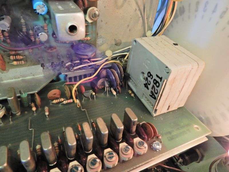
The redesigned selector was made by a company called "Standard-Grigsby". Just one problem. It arrived about the time Tram folded its tent forever. Good luck finding one. And good luck finding the instructions to remove the black selector and install the gray one.
Looks like this once installed.
This is the reason for a seemingly plentiful supply over the years of "incredibly clean" low-mileage Tram 40-channel base radios. It broke before it could get dusty inside, got boxed back up and went on a shelf when the factory's warranty shop closed forever.
There is an end run around this failure. The original wiring of the "Manual", or VFO side of the radio made ONLY the receiver tuneable from that dial. Keying the mike would kick in whatever crystal channel was selected at the time. The VFO gets mixed with one of the 16 MHz crystals on the synthesizer board, but to keep the dial markings accurate, only one of those crystals may be selected when the VFO is active. Tram did this with a couple of switch transistors and switching diodes. Takes the flaky crystal selector totally out of the circuit.
And that's the end run we can take around that flaky crystal selector. By using that switch feature, and bypassing the 'receive-only' factory hookup. Takes that selector totally out of the picture.
There is one caveat to this procedure. It's only been checked for the 'old' D201A. Originally, a slug-tuned coil T100 is where the crystal board feeds into the main receiver circuit board, same as the 23-channel radio.
The later-production D201A has an empty spot on the receiver circuit board where T101 would be, and on the solder side you'll see two small toroid coils and a small trimmer cap for each one. That version may have some wiring differences from the version in this procedure.
This setup will make the clarifier active in receive and transmit both when using the crystal selector. This "locks" the receive and transmit frequencies one to the other.
In manual mode, the clarifier works only in receive mode. The transmit frequency is determined ONLY by the VFO knob.
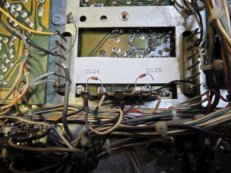
First, make sure that D124 is properly in place and connected. If it's been cut, lap-solder it back, or replace it with a new 1N4148 or equivalent. D125 gets one end cut.
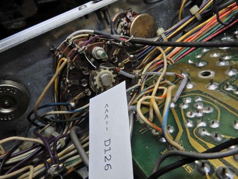
Cut one end of D126, strung across the rear of the mode selector.
The pin numbers of the lugs on S4, the Xtal/Man switch are shown on the factory schematic found at cbtricks.com. I didn't bother to hang numbers on them in the pics.
There is a violet wire on pin 3 of S4. Unsolder it and move to pin 7. This wire feeds below the deck into a diode D124. The one I told you above to make sure is in place.
The clockwise lug of the clarifier control is the top one as the factory installs it, and as seen in pictures. A white/yellow wire that goes from that lug into a wire bundle stays connected here. A second white/yellow wire that disappears into a hole in the chassis deck gets unhooked from the clarifier CW lug. It gets moved to S4 lug #5.
There is a bare wire with a transparent sleeve slid over it connecting the clarifier's CW lug to S4 lug 1. This wire gets removed altogether.
Make sure the three white/blue striped wires are connected to S4 lug 2. Move them there if they aren't already.
Now we'll need two generic 1N4148 type diodes. About any diode will work, even a 1-Amp rectifier like a 1N4007.
One diode gets added with the anode (no band) end on S4#3. Cathode goes to the clarifier CW lug.
The other diode gets the anode end to S4 #5, the cathode end to the clarifier CW lug. One or both diodes may need an extension wire on one end to reach.
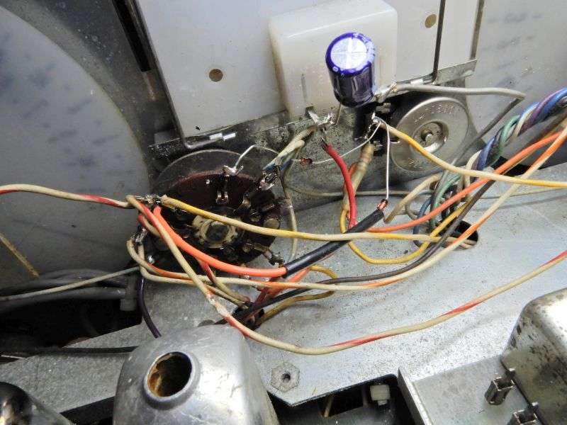
This pic would be clearer if I had moved the radio's S-meter aside. Just disregard the red and gray wires.
They go to the meter, and not to anything connected to S4.
It's not clear in the pic, but a ground wire gets connected to S4 #10, where an orange wire is already found.
So that's the gist of it. The notes I brought home to write this up are missing the steps to set the two trimpots on the crystal board. One of them sets the tuning range of the clarifier control. The other one lines up the transmit frequency in "Man" mode with the 12 o'clock frequency on the clarifier. I'll fetch that and update it later. If I don't upload this right now, who knows when I would get a 'round tuit'?
Biggest drawback of this method is the need to put a frequency counter in line if you want to transmit on frequency. Simply judging that by tuning in the receive side won't quite get you there all the time. But it will let you use the channels that are totally dead on the crystal side.
73
The 'bad' selector was made from black plastic and the housing had sharp square edges and corners. The vendor was "A-MP". Don't need a picture, really.
The redesigned selector was made by a company called "Standard-Grigsby". Just one problem. It arrived about the time Tram folded its tent forever. Good luck finding one. And good luck finding the instructions to remove the black selector and install the gray one.
Looks like this once installed.
This is the reason for a seemingly plentiful supply over the years of "incredibly clean" low-mileage Tram 40-channel base radios. It broke before it could get dusty inside, got boxed back up and went on a shelf when the factory's warranty shop closed forever.
There is an end run around this failure. The original wiring of the "Manual", or VFO side of the radio made ONLY the receiver tuneable from that dial. Keying the mike would kick in whatever crystal channel was selected at the time. The VFO gets mixed with one of the 16 MHz crystals on the synthesizer board, but to keep the dial markings accurate, only one of those crystals may be selected when the VFO is active. Tram did this with a couple of switch transistors and switching diodes. Takes the flaky crystal selector totally out of the circuit.
And that's the end run we can take around that flaky crystal selector. By using that switch feature, and bypassing the 'receive-only' factory hookup. Takes that selector totally out of the picture.
There is one caveat to this procedure. It's only been checked for the 'old' D201A. Originally, a slug-tuned coil T100 is where the crystal board feeds into the main receiver circuit board, same as the 23-channel radio.
The later-production D201A has an empty spot on the receiver circuit board where T101 would be, and on the solder side you'll see two small toroid coils and a small trimmer cap for each one. That version may have some wiring differences from the version in this procedure.
This setup will make the clarifier active in receive and transmit both when using the crystal selector. This "locks" the receive and transmit frequencies one to the other.
In manual mode, the clarifier works only in receive mode. The transmit frequency is determined ONLY by the VFO knob.
First, make sure that D124 is properly in place and connected. If it's been cut, lap-solder it back, or replace it with a new 1N4148 or equivalent. D125 gets one end cut.
Cut one end of D126, strung across the rear of the mode selector.
The pin numbers of the lugs on S4, the Xtal/Man switch are shown on the factory schematic found at cbtricks.com. I didn't bother to hang numbers on them in the pics.
There is a violet wire on pin 3 of S4. Unsolder it and move to pin 7. This wire feeds below the deck into a diode D124. The one I told you above to make sure is in place.
The clockwise lug of the clarifier control is the top one as the factory installs it, and as seen in pictures. A white/yellow wire that goes from that lug into a wire bundle stays connected here. A second white/yellow wire that disappears into a hole in the chassis deck gets unhooked from the clarifier CW lug. It gets moved to S4 lug #5.
There is a bare wire with a transparent sleeve slid over it connecting the clarifier's CW lug to S4 lug 1. This wire gets removed altogether.
Make sure the three white/blue striped wires are connected to S4 lug 2. Move them there if they aren't already.
Now we'll need two generic 1N4148 type diodes. About any diode will work, even a 1-Amp rectifier like a 1N4007.
One diode gets added with the anode (no band) end on S4#3. Cathode goes to the clarifier CW lug.
The other diode gets the anode end to S4 #5, the cathode end to the clarifier CW lug. One or both diodes may need an extension wire on one end to reach.
This pic would be clearer if I had moved the radio's S-meter aside. Just disregard the red and gray wires.
They go to the meter, and not to anything connected to S4.
It's not clear in the pic, but a ground wire gets connected to S4 #10, where an orange wire is already found.
So that's the gist of it. The notes I brought home to write this up are missing the steps to set the two trimpots on the crystal board. One of them sets the tuning range of the clarifier control. The other one lines up the transmit frequency in "Man" mode with the 12 o'clock frequency on the clarifier. I'll fetch that and update it later. If I don't upload this right now, who knows when I would get a 'round tuit'?
Biggest drawback of this method is the need to put a frequency counter in line if you want to transmit on frequency. Simply judging that by tuning in the receive side won't quite get you there all the time. But it will let you use the channels that are totally dead on the crystal side.
73
Last edited:

")