
For the record, I have no desire to bash Troy's Radio or anyone working there, and most especially NOT the brazilian genius who came up with the Arduino firmware.
Bravo!
But no experience of this sort is perfect. Not this one, anyway.
To start, the only specific technical guidance at the moment is for Uniden-made or cloned SSB CB radios with the 8719/8734 PLL chip.
This radio is older than that. The Robyn SB520D is a 1978 design, and has a couple of quirks not found in newer models. Not many, anyway.
Working without specific instructions is, in it's own way, a design job. Until you have all the step-by-step stuff on record so the next guy can just copy it without having to figure any of it out. And that's what this was, a "design the procedure" job.
Of course I snapped pictures of the first attempts for this step and that step. Some of those worked the first time. The ones that didn't work took enough of the day that clear pics of the 'fixed' steps never got collected.
Oops.
The instructions are quite clear that the Arduino Nano controller board can't be powered directly from the radio's 13.8-Volt source. It has its own regulators on board, and that much input voltage will overheat them. This 8-Volt regulator serves to power the DDS from a safe voltage level.
At least it's simple to mount a three-terminal regulator chip in this radio.
The resident firmware for this gadget has every feature that will fit in the kitchen sink. I won't try to detail this here, but here's where it gets explained. http://www.ddsvfo.com
A bunch of external connections get made to the Arduino board for all this. Next time I'll use a chunk of perfboard to support all the external wire connections.
Doesn't qualify as "pretty" by a long shot, but it's the first 858 radio to get this upgrade here.
Didn't get 'beauty' shots of the display as seen from the outside. But here's where the display and encoder get mounted in place of the original LED digits and channel selector.
Troy's Radio supplies only a naked encoder. I used one from fleabay that came with the dark circuit board and header pins. Hooking it up with a 5-pin socket saved time and trouble, compared to lap-soldering five wires to the thing. The OLED display visible here only from behind is set a bit far back from the front-panel window mounted this way, but would look better mounted on some sort of spacer away from the metal panel, closer up behind the front-panel window.
One quirk of this setup is that the controller gets told what mode the radio is in by grounding one or both of two inputs on the Arduino board. The mode selector on the radio selects modes by selecting wires on the hot side. One each for AM, USB and LSB. The instructions suggest placing a NPN transistor's collector on the Arduino's input pin, grounding the emitter and driving current into the base for the mode currently selected. We used 2N3904 transistors, but literaly hundreds of other types would work just as well. A 5.1k resistor goes to the mode-select switch to feed the transistor base, and a second one goes from the base terminal to ground. Using two resistors makes sure the transistor stays shut off when it's not selected.
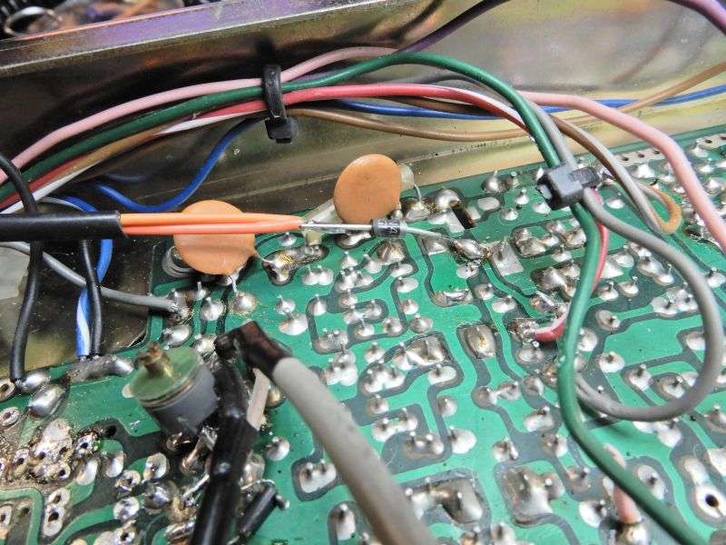
In this pic the upper orange wire (with the black sleeve on it) will select USB mode. The resistor in the foreground with the long bare lead will get a green wire and be used to select AM mode. When there are no active inputs to the Arduino's mode pins, LSB is the default.
Hooking it up this way created an immediate problem. The orange wire coming off of the USB pole of the mode selector switch goes hot when you transmit in AM mode.
Oops. This is built into the radio, since it uses the USB carrier crystal for the AM transmit carrier. Made the Arduino change modes when the mike was keyed in AM.
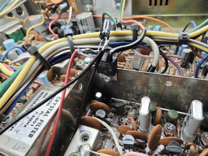
This trick separated the 'USB-only' output from the mode selector from the 'AM-transmit' voltage feeding back out of the circuit board into the orange wire. The second orange wire leads to the USB-mode input pin on the Arduino. The diode blocks voltage on the circuit board from reaching the Arduino's mode input.
Once all this is done, the fun begins. Setting up the offsets and calibration comes next, but you'll have to cover that ground yourself.
And who knows? Maybe they'll come up with a proper procedure for converting the old 858 sideband radios to their DDS setup yet?
73
Bravo!
But no experience of this sort is perfect. Not this one, anyway.
To start, the only specific technical guidance at the moment is for Uniden-made or cloned SSB CB radios with the 8719/8734 PLL chip.
This radio is older than that. The Robyn SB520D is a 1978 design, and has a couple of quirks not found in newer models. Not many, anyway.
Working without specific instructions is, in it's own way, a design job. Until you have all the step-by-step stuff on record so the next guy can just copy it without having to figure any of it out. And that's what this was, a "design the procedure" job.
Of course I snapped pictures of the first attempts for this step and that step. Some of those worked the first time. The ones that didn't work took enough of the day that clear pics of the 'fixed' steps never got collected.
Oops.
The instructions are quite clear that the Arduino Nano controller board can't be powered directly from the radio's 13.8-Volt source. It has its own regulators on board, and that much input voltage will overheat them. This 8-Volt regulator serves to power the DDS from a safe voltage level.
At least it's simple to mount a three-terminal regulator chip in this radio.
The resident firmware for this gadget has every feature that will fit in the kitchen sink. I won't try to detail this here, but here's where it gets explained. http://www.ddsvfo.com
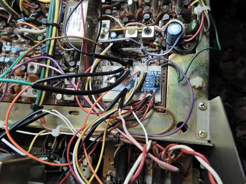
A bunch of external connections get made to the Arduino board for all this. Next time I'll use a chunk of perfboard to support all the external wire connections.
Doesn't qualify as "pretty" by a long shot, but it's the first 858 radio to get this upgrade here.
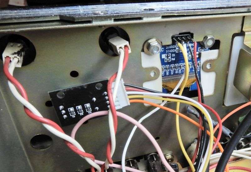
Didn't get 'beauty' shots of the display as seen from the outside. But here's where the display and encoder get mounted in place of the original LED digits and channel selector.
Troy's Radio supplies only a naked encoder. I used one from fleabay that came with the dark circuit board and header pins. Hooking it up with a 5-pin socket saved time and trouble, compared to lap-soldering five wires to the thing. The OLED display visible here only from behind is set a bit far back from the front-panel window mounted this way, but would look better mounted on some sort of spacer away from the metal panel, closer up behind the front-panel window.
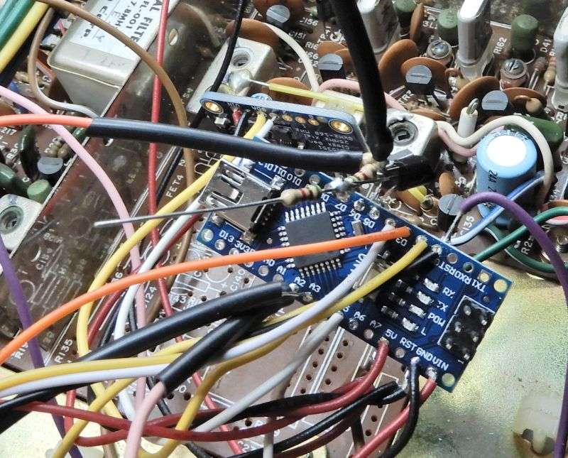
One quirk of this setup is that the controller gets told what mode the radio is in by grounding one or both of two inputs on the Arduino board. The mode selector on the radio selects modes by selecting wires on the hot side. One each for AM, USB and LSB. The instructions suggest placing a NPN transistor's collector on the Arduino's input pin, grounding the emitter and driving current into the base for the mode currently selected. We used 2N3904 transistors, but literaly hundreds of other types would work just as well. A 5.1k resistor goes to the mode-select switch to feed the transistor base, and a second one goes from the base terminal to ground. Using two resistors makes sure the transistor stays shut off when it's not selected.
In this pic the upper orange wire (with the black sleeve on it) will select USB mode. The resistor in the foreground with the long bare lead will get a green wire and be used to select AM mode. When there are no active inputs to the Arduino's mode pins, LSB is the default.
Hooking it up this way created an immediate problem. The orange wire coming off of the USB pole of the mode selector switch goes hot when you transmit in AM mode.
Oops. This is built into the radio, since it uses the USB carrier crystal for the AM transmit carrier. Made the Arduino change modes when the mike was keyed in AM.
This trick separated the 'USB-only' output from the mode selector from the 'AM-transmit' voltage feeding back out of the circuit board into the orange wire. The second orange wire leads to the USB-mode input pin on the Arduino. The diode blocks voltage on the circuit board from reaching the Arduino's mode input.
Once all this is done, the fun begins. Setting up the offsets and calibration comes next, but you'll have to cover that ground yourself.
And who knows? Maybe they'll come up with a proper procedure for converting the old 858 sideband radios to their DDS setup yet?
73
