• You can now help support WorldwideDX when you shop on Amazon at no additional cost to you! Simply follow this Shop on Amazon link first and a portion of any purchase is sent to WorldwideDX to help with site costs.

Dead DX2517

TruckerKevin

KD9NTD
Nov 9, 2017
234
142
53
58
Buckner, Illinois
www.qrz.com
this one has me stumped

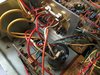
DX2517 no power. Nothing to the switch. Nothing to the power board. I have house current going into the transformer and voltage coming out of it going into the bridge rectifier.

Coming out of the bridge rectifier I have nothing. There are 4 terminals on the bridge rectifier. I have 12.5 on the 2 terminals (yellow wires) coming from the transformer, But the red wire going to the 35v 10000 capacitor has zero voltage. (The final terminal ohms to ground). That should be my main voltage wire?

Bad bridge rectifier? I just got a new one in the mail from rf parts. Same issue. No voltage coming from the bridge rectifier.

Either I got a bad rectifier or I’m not doing something right.

I thought I could bypass it and jump 12 volts from an external 12 voltpower supply to the switch or power supply board and even the main capacitor just for testing purposes but it seems to short so I quit trying before I blow something else
 

Attachments

  • B169996B-A5CD-47E8-A4CB-13521D54F5AE.jpeg
    B169996B-A5CD-47E8-A4CB-13521D54F5AE.jpeg
    2.2 MB · Views: 12

So a bridge rectifier is a device that converts AC voltage to DC voltage.

This should be simple ergonomics.

If I am getting voltage going into the bridge rectifier but I am not getting 12 volts DC coming out of the bridge rectifier, it simply isn't working. And because the new one did not fix the issue, same symptoms, it is a fluke and I got a bad bridge rectifier.

Am I wrong here? Would anyone agree or disagree?
 
Does you multi-meter auto-switch between DC and AC?
The voltage from the transformer (yellow wires) should be A/C, and after the rectifier it should be DC.
If your meter is set to read AC volts, you will have issues reading a DC measurement.

I haven't seen a (new) rectifier arrive busted, doesn't mean it cannot happen though.
Have you checked the main 10,000uF power capacitor or TR603?
 
Last edited:
  • Like
Reactions: kaos513 and Robb
No it doesn’t auto detect, and your probably on to something with those readings. I am still fairly new at this.

But it is set to DC however, and I am not getting any dc voltage from the rectifier. If I am not getting any dc voltage coming out of the rectifier then that has to mean there is a failure coming from either the transformer or rectifier, no?

Or am I wrong?

What I’m not understanding is, in my video my multi meter is set to dc and I am getting 12.5 volts from the 2 wires coming from the transformer, I should not be able to read them at 12.5 dc volts since it’s coming FROM the transformer, which should still be ac current?
 
No it doesn’t auto detect, and your probably on to something with those readings. I am still fairly new at this.

But it is set to DC however, and I am not getting any dc voltage from the rectifier. If I am not getting any dc voltage coming out of the rectifier then that has to mean there is a failure coming from either the transformer or rectifier, no?

Or am I wrong
That's correct.
Have you isolated the rectifier, removed anything that connects to the output of it?
This isolation can help you check the first stage, and remove any possible issues that may be downstream.

Are taking your ground right off the rectifier?
IMO, 12.5V coming out of the transformer is low, after being rectified the voltage can drop, that is a far cry from a regulated 13.8 Volts.
 
Last edited:
So I should unsolder the 2 wires going into the rectifier and check the voltage without being connected to get an accurate reading, using the rectifier ground terminal to ground my probe to. I will do this when I get home.

I’m wondering if I don’t have a bad transformer? 12.5 dc volts coming out of it. I should not have been able to read it at all on dcv settings
 
If you are getting 12.5vac out of your xformer; then you must have the rectifier wired wrong. Look carefully at the rectifier. On two opposite posts, there will be a " ~ " shape; this is where the xformer leads should be connected. The other two posts are your rectified DC out.

Now after you have that straightened out, test the output of the rectifier and find out if it is working and which lead is the negative DC out. This should go to the negative side of the 10,000uf filter cap.

Another thing: you should use the AC setting on your multimeter to be testing the xformer output to get the right voltage reading as Leapfrog pointed out.

ALWAYS be extra careful when dealing with the AC side of ANY power supply!

dx2517_power_supply_sch.gif
 
Last edited:
  • Like
Reactions: TruckerKevin
So I should unsolder the 2 wires going into the rectifier and check the voltage without being connected to get an accurate reading, using the rectifier ground terminal to ground my probe to. I will do this when I get home.

I’m wondering if I don’t have a bad transformer? 12.5 dc volts coming out of it. I should not have been able to read it at all on dcv settings
If you do not present a load to the transformer it will likely give you a higher voltage reading than under normal use, but if something is shorted out "downstream" of the rectifier you wouldn't want a potential short circuit in line, that is why I recommended disconnecting the two wires from the output of the rectifier.

Some meters can read something while on the wrong setting.
 
Last edited:
If the rectifier is wired wrong, the radio came to me like that. I unsoldered them one by one. I also question the 2 capacitors that are bridging the legs together are not without question.

But I have done stupider things. I’ll check and recheck when I get home in awhile
 
I'm thinking that you should have about 28 volts ac (plus or minus a little) coming out of the transformer. The bridge rectifier will take that down to about half. And then the voltage regulator circuitry will take it down to the proper operating voltage for the radio, which is normally 12.7vdc to 13.8vdc.
I just recently worked through the same issues on a base radio with a built in power supply.
 
  • Like
Reactions: TruckerKevin
The rectifier does not appear to be wired up wrong.

The 2 yellow wires coming from the transformer go into the 2 terminals marked "ac"

The red wire comes out of the terminal marked +

The white wire comes out the terminal marked -

With my meter on the 20 ACV setting, I get 12.24 out of one yellow AC wire, I get 11.94 out of the other.

Switch it back to DC volts,

I get nothing out of the red wire marked +
 
You should see about 28 volts ac when connecting your VOM across the two yellow transformer wires.
Connecting the VOM from one yellow lead to ground should show about 14 volts ac, or thereabouts ......
As a matter of fact, I have had to troubleshoot and repair 2 separate base radios in the last 6 months that had built in power supplies. One radio had a bad rectifier, the other had a bad voltage regulator switching transistor that controls the output voltage regulator transistor.
Both radios had transformers that the primary voltage input was 120 volt ac wall plug in. Output voltage coming out was about 28 volts ac going into the rectifier.
 
Last edited:

dxChat
Help Users
  • No one is chatting at the moment.
  • @ Wildcat27:
    Hello I have a old school 2950 receives great on all modes and transmits great on AM but no transmit on SSB. Does anyone have any idea?
  • @ ButtFuzz:
    Good evening from Sunny Salem! What’s shaking?
  • dxBot:
    63Sprint has left the room.