
Not homebrew but restoring a GLA-1000b.
What I am hoping is that someone has one of these on the shelf that can take some pictures of.
It appears that someone thought they could use a different tube in it and never finished the job. My attempt is to restore back to original since I have some 6LQ6 tubes in the shack.
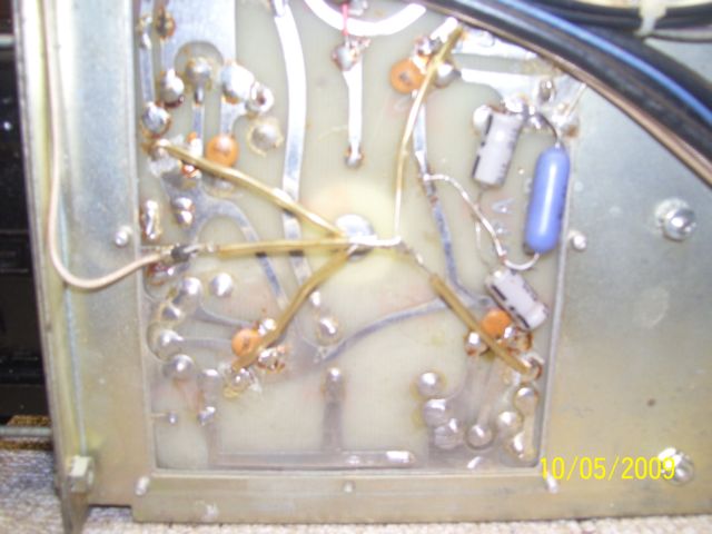
I cleaned up a bunch of solder joints and installed a set of tubes. The diodes in the supply when boom. Looking at the tube board I see that originally (maybe factory) pin 2, 3 and 6 was alltied together with trace. Pin 3 (cathode) has been cut and isolated. Do not know if this is how dentron did it at one time. As you can see in this pic the cathodes are all tied together with hook up wire. A pic of someone else would come in handy here for there is other components I dod not see on this schematic.
Next is the power supply board. It is in the worst mess. All the rectifiers was removed from the board along with the 0.01 caps. A terminal strip was layed in and the rectifiers was installed on it. I am going to rebuild the board back to original so again some top and bottom pics for clarity would come in handy.


The amp has the tuned input board in it all ready. But there are a few wires removed so a pic would also be handy.

I like to see this old thing up and running again. Then I may do a complete rebuild with Far electronic circuit boards and then maybe a Russian tube swap. These were fairly decent desk top amps back in the day.
When I first got it there was a swith on the side for power. Someone blowed out the original swith on the back of the funtion switch. The funtion switch does it all on this amp. When they blew the power switch it also took out the meter movement. I am still looking for a meter. What happened was they installed metal can caps that were to large and one touched the switch wire. I was able to fabricate a new switch and get that part working like the original design.

So I am loading up with projects for the winter.
What I am hoping is that someone has one of these on the shelf that can take some pictures of.
It appears that someone thought they could use a different tube in it and never finished the job. My attempt is to restore back to original since I have some 6LQ6 tubes in the shack.
I cleaned up a bunch of solder joints and installed a set of tubes. The diodes in the supply when boom. Looking at the tube board I see that originally (maybe factory) pin 2, 3 and 6 was alltied together with trace. Pin 3 (cathode) has been cut and isolated. Do not know if this is how dentron did it at one time. As you can see in this pic the cathodes are all tied together with hook up wire. A pic of someone else would come in handy here for there is other components I dod not see on this schematic.
Next is the power supply board. It is in the worst mess. All the rectifiers was removed from the board along with the 0.01 caps. A terminal strip was layed in and the rectifiers was installed on it. I am going to rebuild the board back to original so again some top and bottom pics for clarity would come in handy.
The amp has the tuned input board in it all ready. But there are a few wires removed so a pic would also be handy.
I like to see this old thing up and running again. Then I may do a complete rebuild with Far electronic circuit boards and then maybe a Russian tube swap. These were fairly decent desk top amps back in the day.
When I first got it there was a swith on the side for power. Someone blowed out the original swith on the back of the funtion switch. The funtion switch does it all on this amp. When they blew the power switch it also took out the meter movement. I am still looking for a meter. What happened was they installed metal can caps that were to large and one touched the switch wire. I was able to fabricate a new switch and get that part working like the original design.
So I am loading up with projects for the winter.
")
