• You can now help support WorldwideDX when you shop on Amazon at no additional cost to you! Simply follow this Shop on Amazon link first and a portion of any purchase is sent to WorldwideDX to help with site costs.

Difference in AstroPlane vs. New Top One per Eznec5

didn't you notice? free cell has been banned....just adding a little humour to the thread, sometimes you need that!!!

but really i agree with homer, i just don't see what he was talking about. I'll keep an open mind and study it for a while.
 
Yes. the center coax conductor is isolated at the top of wire 4, and the coax braid is not. It is grounded to the mounting strap/hub.
That to me is a classic method of building a common 1/2λ dipole. . . split the coax to each of the dipole 1/4λ poles, no?

IMG_2006.jpg


You'll notice on Starduster's model the connector is isolated to the center conductor for contact to wire 4, but the shield is directly connected to the hub via the bolts holding it together.

I know you're right, my bad.
 
eddie,
for a better understanding of transmissionline mode currents read the open sleeve antenna article in the arrl,
CEBIK also gives some clues in his "some j-poles that i have known" article,

the astroplane needs the mast or coax to form the transmissionline, its in the patent and won't work without it,
the relative conductor diameters / spacing and flare control impedance,

avanti claim the flare also controls takeoff angle as does mast length.
 
It is with reference to the folded 3/4 wave AP. You can click on the little arrowhead in front of Freecell's user-name in the quote in my post #103 and read it in context.

NB, I'm ususally not one to belabor a point, in the long run they matter little except that one gets out, and as well as they can with a given antenna. . . however, I know from whence your quote came since I have read that thread more than once, and a good one it is.
The problem with it in the thread it originated, and in this is, both of them highlighting the Astroplane antenna, is that the AP is not 3/4 to start with, so say its makers, and to start from the presumption of it being so and attempt to make it so by unraveling the physical lengths of the radiators so it appears so doesn't change things. Notice in the quote that the attempt to prove it a 3/4 wave assumes it is, but uses the physical dimensions of what Avanti called a 1/4 wave radiator comprised of a folded element. If that logic did work, then you would have a full wave antenna, one side made by unfolding the 1/4 wave radial, and the other, since we are counting all lengths, made up of the 1/4 hat + 1/4 vertical. . .
 
eddie,
for a better understanding of transmissionline mode currents read the open sleeve antenna article in the arrl, CEBIK also gives some clues in his "some j-poles that i have known" article, the astroplane needs the mast or coax to form the transmissionline, its in the patent and won't work without it,
the relative conductor diameters / spacing and flare control impedance,
avanti claim the flare also controls takeoff angle as does mast length.

I agree Bob, but for my better understanding, aren't transmissionline mode currents (TMC) out-of-phase and similar to what goes on inside of coax, and not radiating. Aren't they the opposite of antenna mode currents, which are in-phase and radiating...just like I describe earlier in my examples of the currents on a dipole vs. the bottom of a 5/8 wave?

If this is so, don't these TMC currents tend not to contribute to radiation due to cancellation?
 
NB, I'm ususally not one to belabor a point, in the long run they matter little except that one gets out, and as well as they can with a given antenna. . . however, I know from whence your quote came since I have read that thread more than once, and a good one it is.
The problem with it in the thread it originated, and in this is, both of them highlighting the Astroplane antenna, is that the AP is not 3/4 to start with, so say its makers, and to start from the presumption of it being so and attempt to make it so by unraveling the physical lengths of the radiators so it appears so doesn't change things. Notice in the quote that the attempt to prove it a 3/4 wave assumes it is, but uses the physical dimensions of what Avanti called a 1/4 wave radiator comprised of a folded element. If that logic did work, then you would have a full wave antenna, one side made by unfolding the 1/4 wave radial, and the other, since we are counting all lengths, made up of the 1/4 hat + 1/4 vertical. . .
Sorry Homer but I totally disagree. I read the patent and it refers to two 1/4 waves, one per side of the ring, plus one more made by the top 1/8 wave plus it's cap hat which they claim equals a 1/4 wave, the 3rd 1/4 wave or 3/4 wave total.
I also read that you can remove the top 1/8 + cap hat element, extend the mast up 1/4 wave above the mounting plate and it will perform similarly, though not preferably.
 
NB, I'm ususally not one to belabor a point, in the long run they matter little except that one gets out, and as well as they can with a given antenna. . . however, I know from whence your quote came since I have read that thread more than once, and a good one it is.
The problem with it in the thread it originated, and in this is, both of them highlighting the Astroplane antenna, is that the AP is not 3/4 to start with, so say its makers, and to start from the presumption of it being so and attempt to make it so by unraveling the physical lengths of the radiators so it appears so doesn't change things. Notice in the quote that the attempt to prove it a 3/4 wave assumes it is, but uses the physical dimensions of what Avanti called a 1/4 wave radiator comprised of a folded element. If that logic did work, then you would have a full wave antenna, one side made by unfolding the 1/4 wave radial, and the other, since we are counting all lengths, made up of the 1/4 hat + 1/4 vertical. . .

Homer, I don't agree with NB on this one either. Don't you guys listen to Bob talk about antenna mode currents and transmission line mode currents? These currents either radiate or they don't...for the most part that is. Nothing is 100%, so both modes go on and vary at times.

I just posted a CF 1/2 wave dipole vs. 5/8 wave and the currents they produce per Bob's request. You will note that both models give a clue as to what happens with antennas due to phase. They either radiate a portion of the antenna being in-phase or they don't radiate the portion being out-of-phase. If I'm right, then this business is pretty simple.

A while back we argued the Vector/Sigma4 deal. Some were claiming the Vector/Sigma4 antenna is a 1/2 wave J-pole, and some were claiming it's a 3/4 wave radiator. The big difference and the big argument was settling on whether the bottom radial basket of the antenna radiated or not, and that is about the gist of the idea. For me that discussion explains the issue pretty simply, one way or the other.

My Sigma4 model shows the bottom 1/4 wave cage is radiating, is in-phase with the top 1/2 wave, and thus it is a 3/4 wave antenna.

With Shockwave's assistance Sirio produced similar reports and ideas showing the bottom basket is in phase and radiating with the top 1/2 wave radiator, even though their manual claims their New Vector 4000 is a J-Pole.

The typical J-pole is 3/4 wave long physically, due to the bottom 1/4 wave tuner section, being two end-to-end 1/4 wave radiators (a 1/2 wave dipole) folded back over on itself, side-by-side and parallel with one another. Thus the relationship at the bottom becomes, out-of-phase and does not radiate, thus leaving the top 1/2 wave to radiate, thus it is a 1/2 wave antenna, and is pretty well undisputed in the world of antennas.

IMP, in order to figure out what an antenna is, we have to try and understand how the elements relate regarding current phase.
 
if the tm currents are of the same phase and magnitude they don't cause radiation, when the currents are shifted in phase or magnitude you get common mode radiation,
it may not be the full story of the astroplane but i don't think we can ignore it and opt for a simple explanation.

as to the sigma, don't forget mr CEBIK said the sleeve could radiate in phase with the upper 1/2wave in a none aparent to most people co-linear manner,
the short leg of a j-pole radiates very little with close spaced conductors but causes some radiation with wider spacing = the lobsided pattern.
 
Sorry Homer but I totally disagree. I read the patent and it refers to two 1/4 waves, one per side of the ring, plus one more made by the top 1/8 wave plus it's cap hat which they claim equals a 1/4 wave, the 3rd 1/4 wave or 3/4 wave total.
I also read that you can remove the top 1/8 + cap hat element, extend the mast up 1/4 wave above the mounting plate and it will perform similarly, though not preferably.

NB, IMO there are three elements that can radiate currents in the bottom section below the hub of the A/P. The loop will not radiate due to half of the segments in its circumference being out-of-phase, thus we have cancellation with the hoop.

This leaves three elements in the bottom, two are equal phase and one is opposite, so two cancel leaving one 1/4 wave element that is in-phase with the top shortened element and its in-phase top hat, making a total of two 1/4 wave in-phase elements doing the radiation, thus it is a 1/2 wave antenna.
 
if the tm currents are of the same phase and magnitude they don't cause radiation, when the currents are shifted in phase or magnitude you get common mode radiation,
it may not be the full story of the astroplane but i don't think we can ignore it and opt for a simple explanation.

as to the sigma, don't forget mr CEBIK said the sleeve could radiate in phase with the upper 1/2wave in a none aparent to most people co-linear manner,
the short leg of a j-pole radiates very little with close spaced conductors but causes some radiation with wider spacing = the lobsided pattern.

Bob aren't these statements a contradiction.

The phase of currents inside a coaxial feed line are out-of-phase and do not typically radiate. A 1/2 wave radiator is in-phase and it does tend to radiate. I agree with the Cebik claim, but not the one above unless TM currents, whatever they are makes the difference.

I've heard of displacement currents that maybe were inconsequential, but not TM currents. Me thinks there are just too many currents flowing in this business to keep up.
 
Last edited:
yes they are, i meant to say opposite phase equal magnitude causes no radiation, as the relative phase or magnitude shifts you get radiation afaik.
 
...and don't forget the 95% VF of aluminum in air ;)

I'm 10-10 on the side. :laugh:


:pop:
 
Homer, this is going to get confusing. I can't remember if I posted models showing the results of changing the bow on the A/P, but I know we talked about it. The patent and common idea is that such adjustments to the bow in the radials changes the impedance, and can also change the elevation for the maximum angle. It makes sense that we can see change in match and resonance by testing, but we really can't tell changes in the gain and angle...even if it does change.

These models do show the similar moves as you made changing the bow, but they do not change the strap position on the radials. I changed the strap length, and it appears to be changing the impedance, but I see it as an obvious change in frequency, just like you described using your 259B. When that happened we didn't talk about the match so much, we discussed the frequency and that is what your meter was showing us.

This said, right or wrong, these adjustments do not indicate any change in pattern's best low angle lobe, the part we can't easily see or likely tell for sure...in our real world testing.

I see the narrowing of these radials as improving the match to its best compared and including the 12.5" dimension for my "to spec" model and the 22" wide spaced model which I think was supposed to send the angle down well below the horizon.

In this regard, I don't remember what your actual matching changes were using your 259B I was considering only frequency and resonance I think. This issue of match vs. resonance can get confusing trying to understand and prove what causes what. I have mixed feelings on what I've done here, and I didn't realize it until I started writing about how and what I saw.

Non-the-less, here are the overlays for the three models detailed below.

AstroPlane overlay.jpg

First model is my "to spec" model that has the strap dimension, 12.5", the same as my Top One A/P model.

Second model the strap is only adjusted to simulate the radials are 10" apart.

Third model the strap is only adjusted to simulate the radials are 22" apart.

These changes were all made at the same point on the antenna and this did not move the strap, the strap length was changed, see further explanation below.

View attachment AstroPlane tuned with radials space.pdf

Note: I considered the fact that my adjustments were all made at the same height on my model, and maybe that is what the patent is saying instead of moving the strap change the bow. Per se my strap did not move, but the bow did change for this example. Did Avanti tell us that the location of the bow was what was important or did the tell us the bow is what made the difference? At this point I'm a bit confused and I might have to do a lot more work to physically move the strap up or down keeping the strap the same size as I go.

I did the models this way, because Eznec will not let me make anything but a straight line or a loop of some dimension, but the loops are made using very small straight lines to simulate the arc, so I'm still limited to straight lines. The arc on the A/P radials has to be done using two wire for each side of the antenna as a result in creating the bow, albeit they are the same diameter wires.

The real antenna is not made adjustable in this area, but Homer your's is, so you move the strap to change the bow, but is this what Avanti was talking about or were they telling us the bow was what mattered and they put it at the best spot in their product.

I was thinking the bow was what made the difference and such an adjustment was easy with the model by changing the strap length. I might have to consider that the length of the two radials, bottom and top if I want to make changes as you moved your strap. I discounted this idea, because the elements are the same size and the moves are small, like 1" at a time just change the bow a little. Your antenna was left with the same total length of each radial and so is my model.

Homer if you understand the is issue as I have attempted to describe, then maybe you or others might consider if it's an issue or not, and let me know what you think.

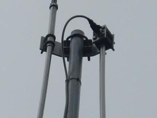
Is the strap on your A/P adjustable?

Personally, I think working with this model...it would be a lot easier to change frequency adjusting the top hat. However, I haven't studied the effects on the match, gain and angle if any...by doing that. I know it will change frequency if we wanted.

The A/P has a lot of good matching bandwidth to work with.
 

dxChat
Help Users
  • No one is chatting at the moment.