Hey all. Was just wondering if a rumor i heard is true that power is divided between the 2 antennas? So lets say you have 100watts, that 100watts will be split into 50watts per antenna. Even if it was true, wouldn’t it still equal out to 100watts on tx?

You are using an out of date browser. It may not display this or other websites correctly.
You should upgrade or use an alternative browser.
You should upgrade or use an alternative browser.
-
You can now help support WorldwideDX when you shop on Amazon at no additional cost to you! Simply follow this Shop on Amazon link first and a portion of any purchase is sent to WorldwideDX to help with site costs.
-
A Winner has been chosen for the 2026 July 4th Retevis RA89R Giveaway! Click Here to see who won!
Dual antennas
- Thread starter Cahtrina
- Start date

Yep..minus any losses.Hey all. Was just wondering if a rumor i heard is true that power is divided between the 2 antennas? So lets say you have 100watts, that 100watts will be split into 50watts per antenna. Even if it was true, wouldn’t it still equal out to 100watts on tx?
IT's a little more complex than that but what you might want to study is how two antennas...
Spaced apart in specific distances from each other - their individual waves radiating from themselves - can generate a signal pattern that enhances both...

Constructive and Destructive
interference patterns give two antennas
fed off the same radio - a radiation pattern
that can enhance the ability to use two antennas,
to receive signal in specific directions.
Spaced apart in specific distances from each other - their individual waves radiating from themselves - can generate a signal pattern that enhances both...
Constructive and Destructive
interference patterns give two antennas
fed off the same radio - a radiation pattern
that can enhance the ability to use two antennas,
to receive signal in specific directions.
In all these examples to achieve any controlled directivity the antennas must be a minimum of 1/4 wavelength apart, and "phasing line" as stated.
Less spacing results in pattern distortion and loss. IMHO
Last edited:
That's interesting. The power divides, but the the total radiating surface has doubled. Would that be a 3db gain?
the answer to that question is solely dependent on the radiation efficiency, (or lack thereof) the spacing and the predominance of constructive interference over destructive interference between the individual antennas forming the final pattern based on the first two parameters listed above as well as the type of antennas being used.
there's a full page in the phased vertical antennas section of this book with 40 different spacing and phasing combinations (pictures) and the resulting patterns. you can pick the pattern that you want and build a phased array from scratch if you're so inclined and motivated.
you're looking specifically for the chapter on multielement arrays. in the 15th edition that would be chapter 8, pages 8-6 and 8-7.
1974 The ARRL Antenna Book
(PDF File size: Very Large File - 41.1M)
https://www.smcelectronics.com/DOWNLOADS/1974-ARRLANT.PDF
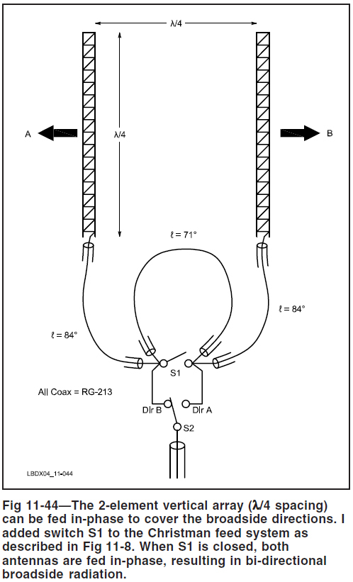
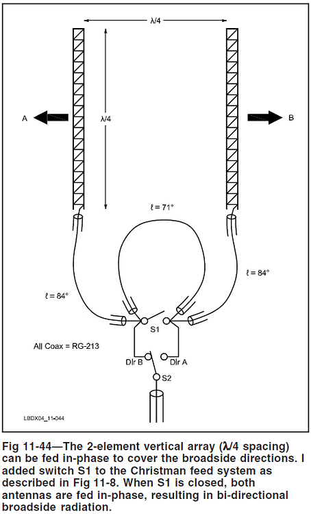
here are just a few: the antennas are at the opposite ends of the vertical plane (north, south) and the radiated signal is broadside (east, west) to the plane of the antennas.

2000 The ARRL Antenna Book
(PDF File size: Very Large File - 39.0M)
https://www.freebooksdrive.com/the-arrl-antenna-book/
Last edited:
Having used a full size 1/4 wave ground mounted (2) verticals w/spacing to achieve ( black figure 3) pattern for 80/160m(barracuda pattern)
One must remember achieving directivity, in those patterns creates equall or Greater Nulls opposite those greater peak directions. Thus even with no delay shifts, the null created at 90 degs to antenna is very deep.
I remember experimenting with "Dual Phased" antennas on a pick-up I had. I also set-up the same for couple other operators. The key to remember was I never got max signal forward/rear, the max always resembled the pattern on lower left figure Freecell displayed.
The corners were always stronger than straight front/rear, I always attributed this to the pattern distortion created by the less than quarter wave spacing on a pick-up. Hard to get spacing like 104 inches apart (in the clear) as any cab, body parts would cause pattern distortion.
Thus you spent a great deal of time trying to achieve the front/rear pattern, only to find out you still had one direction seemed to prove better than all the rest. I always found one of the "rear" corners were the "Hot" spots.
Trying to create this(strongest front/rear) pattern on Semi rig would be almost impossible in the truest sense.
VHF/UHF frequencies were better suited for that front/rear pattern than any frequency below say 50 MHz
So my worthless 2 cents.

All the Best
Gary
One must remember achieving directivity, in those patterns creates equall or Greater Nulls opposite those greater peak directions. Thus even with no delay shifts, the null created at 90 degs to antenna is very deep.
I remember experimenting with "Dual Phased" antennas on a pick-up I had. I also set-up the same for couple other operators. The key to remember was I never got max signal forward/rear, the max always resembled the pattern on lower left figure Freecell displayed.
The corners were always stronger than straight front/rear, I always attributed this to the pattern distortion created by the less than quarter wave spacing on a pick-up. Hard to get spacing like 104 inches apart (in the clear) as any cab, body parts would cause pattern distortion.
Thus you spent a great deal of time trying to achieve the front/rear pattern, only to find out you still had one direction seemed to prove better than all the rest. I always found one of the "rear" corners were the "Hot" spots.
Trying to create this(strongest front/rear) pattern on Semi rig would be almost impossible in the truest sense.
VHF/UHF frequencies were better suited for that front/rear pattern than any frequency below say 50 MHz
So my worthless 2 cents.
All the Best
Gary
phased 20 meter 1/4λ verticals @ 1/8λ spacing & 135° feed.
produces an inline cardioid pattern w/ 4.1 dB. of forward directivity
& good to excellent (deep null) front-to-back signal rejection.
cardioid azimuthal radiation pattern looking
down from directly overhead of the array.

according to the video, 0°=SW and 180°=NE.
(KI6WJ in Nevada)
https://n5oe.net/index.php?id=20m-phased-vertical-test-setup
https://www.n5oe.net/data/uploads/20mPhasedArrayKH6.m4v
https://www.n5oe.net/data/uploads/KI6WJf_b.m4v
@ 1/8λ spacing from 0° to 180° (0°, 45°, 90°, 135° & 180°) feed there are
five different patterns that can be generated, everything from omnidirectional
to cardioid to a bidirectional pattern much like the pattern broadside to a
horizontally polarized dipole, only inline with the antennas, not broadside.
produces an inline cardioid pattern w/ 4.1 dB. of forward directivity
& good to excellent (deep null) front-to-back signal rejection.
cardioid azimuthal radiation pattern looking
down from directly overhead of the array.
according to the video, 0°=SW and 180°=NE.
(KI6WJ in Nevada)
https://n5oe.net/index.php?id=20m-phased-vertical-test-setup
https://www.n5oe.net/data/uploads/20mPhasedArrayKH6.m4v
https://www.n5oe.net/data/uploads/KI6WJf_b.m4v
@ 1/8λ spacing from 0° to 180° (0°, 45°, 90°, 135° & 180°) feed there are
five different patterns that can be generated, everything from omnidirectional
to cardioid to a bidirectional pattern much like the pattern broadside to a
horizontally polarized dipole, only inline with the antennas, not broadside.
Last edited:
I've thought about using a 3/4 electrical wavelength of coax (velocity factor) fed from the input of the 1st quarter wave to feed a second quarter wave. It would take some tuning I'm sure but as far as signal phasing goes, this would in effect give you 2 quarter wave antennas (Mobile) operating in series as a half wave radiator.
If my beer drinking induced idea holds water, then the second antenna would be radiating a signal starting at its feed point exactly where the 1st antenna stops.
A picture would be better I'm sure. But running 2 antennas in series and having the actual signal aligned so they time aligned would have to work.
Double the radiating surface and still omnidirectional basically.
And if this could be done all with 50 ohm coax and it still present a 50ohm load then there'd have be a gain factor to be had.
"Trucker" co-phase harnesses are supposed to be 100 ohm and 100 ohm feedlines combined and fed with 50 ohm coax. And a certain length to if I recall.
When I was in high school in the late 90s I ran 2 A99s and was able to walk the pattern around by adding 1/4 wavelengths (electrically) to one of them and it worked great. Could really send the signal North, South, East and West. Or drive them in time and get the typical figure 8 pattern.
Eventually needed that spot on the roof for a beam and went with a 5/8 wave.
dxChat
- No one is chatting at the moment.