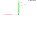
So here I will start with a base model that shows a half wavelength antenna in a worst case scenario.
View attachment 72895
In this case, the circle is the feed point. Everything above it represents the antenna, and everything below it represents the feed line.
The green curved line is the current distribution on the model, the further away from the antenna the stronger the current is on that part of the antenna. Essentially, for this antenna, you want to get all of it, or at least as much as possible, above the feed point. Anything below that point almost always (except a few rare instances) works against you, and your efforts to make contacts.
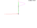
Next is a model of the same antenna with the choke right below the feed point.
View attachment 72896
The blue box is the choke, and in the models shown here it is 9000 ohms, simulating an air choke.
In this case it has some effect, but could be better. I've made models in the past where putting a choke in this spot did almost nothing. This difference is either related to the new (to me) nec 5 engine calculating currents differently, or me not finding the exact right lengths for this antenna model in the short time I'm putting these together.
We definitely still have common mode currents, although definitely less of them.
And finally, 1/4 wavelength down from the feed point.
View attachment 72897
Here we see a few common mode currents above the choke, but essentially none below the choke. This is, to me, a more desirable current distribution. Using past models, I can actually use far less than 9000 ohms and get the same result as this. The reason for this is chokes are a current devices, essentially they resist the flow of current. Because of this, they tend to be more effective where the current is at its maximum on the antenna.
I hope this helps explain why I say to choke the a99 1/4 wavelength down from the feed point.
The DB
")


")