
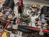
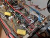
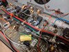
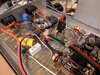
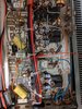
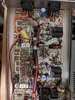
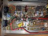
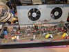
Got this amp from a very good friend who fell SK several years ago and it's been on the shelf since. Decided to dust it off and perhaps put it in the mobile. Thought I should pop it open and make sure everything is kosher before I hook it up. Looks okay to me, but lets be real, what do I know? So I put it to the readers of WWDX, anything unusual or alarming I should correct? What is that brown round thing with one wire coming off of it? Looks like it used to have something soldered onto the other tab.
What kind of drive should I be putting into this? Thinking output should key around 200-250W, x4 on peaks.
Thanks!
What kind of drive should I be putting into this? Thinking output should key around 200-250W, x4 on peaks.
Thanks!
Attachments
-
 IMG_20201106_232812.jpg989.5 KB · Views: 446
 -
 IMG_20201106_232716.jpg1 MB · Views: 414
 -
 IMG_20201106_232705.jpg1 MB · Views: 421
 -
 IMG_20201106_232658.jpg972 KB · Views: 422
 -
 IMG_20201106_232637.jpg961.5 KB · Views: 393
 -
 IMG_20201106_232628.jpg954 KB · Views: 403
 -
 IMG_20201106_232607.jpg1.2 MB · Views: 423
 -
 IMG_20201106_232548.jpg1 MB · Views: 432
