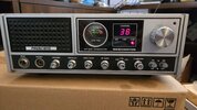
Hello all. Just picked up a super clean President Washington manufactured in Japan in late 1977. I friend gave it to me for free. Only issue I'm seeing with it is when on SSB and the NB is pushed in signals sound slightly garbled and when the NB is off the SSB signals sounds good and clean. Radio has not yet been re-capped. Anyone know what electrolytic cap works in the NB circuit? I'm pretty sure that might be the audio problem. Thanks.

You are using an out of date browser. It may not display this or other websites correctly.
You should upgrade or use an alternative browser.
You should upgrade or use an alternative browser.
-
You can now help support WorldwideDX when you shop on Amazon at no additional cost to you! Simply follow this Shop on Amazon link first and a portion of any purchase is sent to WorldwideDX to help with site costs.
-
A Winner has been chosen for the 2026 July 4th Retevis RA89R Giveaway! Click Here to see who won!
Early President Washington D858
- Thread starter HavaV10
- Start date

Could be that the blanker is just aligned wrong. A radio that old has likely been tweaked by someone who doesn't know just what each tuning slug is for. L1 and L2 are peaked using a 23.5 MHz signal from the signal generator. Can't be done by tweaking a slug while watching the S-meter. Takes a 'scope probe on a test point.
The Realistic TRC-449 uses the same circuit board. Same alignment procedure.
It's on page 17 of the service manual here: https://cbtricks.org/radios/realistic/trc_449/graphics/realistic_trc_449_sm.pdf
There were two versions of the noise blanker in those radios. Only the first version of the blanker is covered in that manual. The later one has a "high rise" pc board just to the right of L2. Never have seen a diagram for that version.
Naturally this radio is old enough to benefit from being recapped. The blanker circuit contains only one electrolytic cap, C605 a 0.1uf part. I'm not convinced it's causing your distortion problem. If sideband receive audio sounds okay with the blanker turned off, a capacitor is probably not the culprit. A kit of electrolytic caps for that radio contains 36 of them, if memory serves.
A radio with 500 original miles might not have any bad ones in it.
Yet. But operating stresses will remind them how old they are before long. And a high-mileage radio is bound to have several that no longer meet performance specs.
Not a matter of if but of when.
73
There is another electrolytic associated with the NB, C211 in the AGC circuit. The AGC controls the bias of the NB pulse amp.
I was going to say the same thing, replace them all. They are 48 years old.
I was going to say the same thing, replace them all. They are 48 years old.
l think L1 got peaked for 27 MHz and the sideband signal is blanking itself. The blanker in the Tram D201 would do that on really strong signals. Tram's advice was that anybody that loud doesn't need a noise blanker to hear them.
It's still kinda nice to blank the buzz when the loud station unkeys.
73
It's still kinda nice to blank the buzz when the loud station unkeys.
73
can it really be tuned that far?l think L1 got peaked for 27 MHz and the sideband signal is blanking itself.
73
Yea, I just tried to do the math, if I am doing it right, it looks like it only has to go a quarter of a nH with that 39pF series cap. Thanks!
edit: wait, thats like a mm of wire. I dont know how to figure that out, maybe there is a cap inside that first can, but I believe you lol
edit 2 lol, maybe i did it right, that was to the -6, not -9, so thats uH's
a quarter of a uH.
I had one of my "moments" there lol
edit: wait, thats like a mm of wire. I dont know how to figure that out, maybe there is a cap inside that first can, but I believe you lol
edit 2 lol, maybe i did it right, that was to the -6, not -9, so thats uH's
a quarter of a uH.
I had one of my "moments" there lol
Thank you Mr. NomadCould be that the blanker is just aligned wrong. A radio that old has likely been tweaked by someone who doesn't know just what each tuning slug is for. L1 and L2 are peaked using a 23.5 MHz signal from the signal generator. Can't be done by tweaking a slug while watching the S-meter. Takes a 'scope probe on a test point.
The Realistic TRC-449 uses the same circuit board. Same alignment procedure.
It's on page 17 of the service manual here: https://cbtricks.org/radios/realistic/trc_449/graphics/realistic_trc_449_sm.pdf
There were two versions of the noise blanker in those radios. Only the first version of the blanker is covered in that manual. The later one has a "high rise" pc board just to the right of L2. Never have seen a diagram for that version.
Naturally this radio is old enough to benefit from being recapped. The blanker circuit contains only one electrolytic cap, C605 a 0.1uf part. I'm not convinced it's causing your distortion problem. If sideband receive audio sounds okay with the blanker turned off, a capacitor is probably not the culprit. A kit of electrolytic caps for that radio contains 36 of them, if memory serves.
A radio with 500 original miles might not have any bad ones in it.
Yet. But operating stresses will remind them how old they are before long. And a high-mileage radio is bound to have several that no longer meet performance specs.
Not a matter of if but of when.
73
Mr. Nomad, hey I looked and looked and I just can't find C605. The PCB is a PC-196AB Uniden. Spent over 20 minutes and couldn't locate that C605 Cap. Help please.
Might be a production change between the diagram and your radio. The schemo says the positive side of C605 goes to the cathode of D602, and the negative side to ground. If yours doesn't have the tiny "mezzanine" pc board PC244 right next to L2, this part of the TRC449 is different from yours.
73
73
I didn't see C605 either. I think the 449 schematic is a little different.
If I recall, President had a Service Bulletin for the 858 Washington and Grant for adding that circuit board, from the 449, to the Noise Blanker circuit. It also contained other modifications as it was several pages long.
I think I found what you are talking about in my files.If I recall, President had a Service Bulletin for the 858 Washington and Grant for adding that circuit board, from the 449, to the Noise Blanker circuit. It also contained other modifications as it was several pages long.
Edit: added side by side

Attachments
Last edited:
There are several Mistakes/Omissions in the TRC449 Schemo. Especially in the driver/final area. Maybe others too.
I didn't see C605 either. I think the 449 schematic is a little different.
J.J. 399
dxChat
- No one is chatting at the moment.