• You can now help support WorldwideDX when you shop on Amazon at no additional cost to you! Simply follow this Shop on Amazon link first and a portion of any purchase is sent to WorldwideDX to help with site costs.

Early Zachary T- no Tx or Rx, VCO problem.

Night Stalker10

New Member
Mar 30, 2026
21
6
3
67
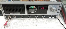
Hello, I have been working on a Zachary T off and on for awhile with a no transmit or receive problem. I'm not a real tech, but I have enjoyed fixing a few cb radios over the last few years. This was listed as a tech special on Ebay, and it has been a bigger challenge than I thought it would be. Looking at the solder, no one has touched this radio since it was built, until I got it. The first thing to do on a 50 year old radio was to clean it up and I used deoxit on the control pots on the front of the radio. I also re-capped the radio, because I found a few capacitors that were way out of spec. This radio has the PCB PC-198AB. I can't find any info on this board, so I assume it has different parts installed from the factory than the PC-198AA board. I did have to replace the VCO L20 can because the old wax had messed up the plastic threads and I couldn't adjust the VCO voltage. Also I replaced the L24 can because when I did have recieve, I couldn't adjust the 37.880 mhz signal (on ch19) at TP 6. Eventually I decided It must be IC5 VCO uhic-004 modual. i can't find any info on this 10 pin modual other than it has 2 substitute numbers of NTE 1203 and ECG 1203. I orderd the NTE 1203 off Ebay, and it didn't work after i Installed it. Eventually the RX came to life while checking other components. I noticed the voltage at TP 5 was high around 3.6 volts, I should have left it alone, because when I adjusted the voltage to 3 volts per the sams manual, I lost the RX and TX again. I decided to order the ECG 1203 modual and it hasn't worked at all.

Basically where I'm at with my trouble shooting is that lock pin 1 on the upd858c pll is 2.2 volts. It should be close to 0 volts to lock in. Here's the mystery part, pin 1 of IC5 VCO should be around 3 volts, but its 200-300 mv. This pin also feeds the collector of TR17 PLL stop transistor (2sc945 which I replaced), with 200-300 mv dc instead of the 3 volts. TR17 has .7 volts on the base. I forgot to mention all the voltages on VCO IC5 are correct, except for pin 1. It's been a mystery to me as to why the 3 volts are missing on pin 1. I've tested the L21 can and it test okay, it also worked when the radio had TX and RX, I could adjust the signal to max using the O'scope. I first thought the 3v for pin 1 was maybe being provided the Pin 1 on IC5, but then I realized it's probably being feed by R117. On R117 (560 ohm) it has a Vcc supply of 4.7 volts, but on the other lead of R117 the voltage is on 300 mv that goes through L21 to Pin 1 of IC5. I did test and replace C143 also, but no difference. Even with Pin 1 of IC5 desoldered, it only shows around 300 mv on that trace from L21. One other possability that maybe clamping down the 3 volts, is the channel selector. It looks like the channel selector is tied to the base of TR17 by a yellow wire, and also to D16 to LD pin 1 of PLL iC3. The channel selector works fine and all the digits are readable, so I assume its okay??

One last thing to mention. With a s9 signal (-67db) to the radios antenna jack, I can inject a 37.880 mhz 200 mv signal from my Owon signal generator to TP6 and the receiver comes to life. Also it shows around an s-4 signal on the radios meter. This proves to me that all the components in the receivers section is fine. Sorry for the long post, but I was hoping that maybe someone has seen this problem before either with this chassis, or with a simular one. I should also mention that i've been using my 13.8 variable bench power supply instead of the 120v radios power supply. Just to rule out any strange voltage behavior. I've spent a lot of time researching this, and it seems like any utube videos with a Zachary T no TX or RX problem was fixed by doing a full re-cap of the radio. Thanks.. Warren.
 

Attachments

  • IMG_20260502_112924661.jpg
    IMG_20260502_112924661.jpg
    1.9 MB · Views: 6
Last edited:

Even with Pin 1 of IC5 desoldered, it only shows around 300 mv on that trace from L21.
This voltage is low because TR17 is pulling it down in response to the LD signal being high. The radio is out of lock. When that is corrected, TR17 will no longer pull down the voltage at pin 1. Resolder pin 1, it does not have to be disconnected to troubleshoot this.

I did find a datasheet for the ECG1203, but I don't think the VCO is the problem. I would put the old one back in (since it worked at 3.5v and we know it works). Here is that datasheet for the 1203 and similar.

You say you replaced L24. I am wondering if the tuning on that isn't set right. I assume what is shown as a 36MHz crystal is really a 12MHz crystal and that tuned transformer sets the output to the third harmonic. If that is not tuned right, there may not be enough power going to the mixer for the PLL VCO loop to function correctly. Try to peak L24 with a 10x probe on the secondary side that goes to the mixer gate..

Try adjusting L20 again. If it locks at any voltage, see what frequency the VCO is running at. Maybe someone did a channel mod over at the binary side.
 
  • Like
Reactions: Gman
This voltage is low because TR17 is pulling it down in response to the LD signal being high. The radio is out of lock. When that is corrected, TR17 will no longer pull down the voltage at pin 1. Resolder pin 1, it does not have to be disconnected to troubleshoot this.

I did find a datasheet for the ECG1203, but I don't think the VCO is the problem. I would put the old one back in (since it worked at 3.5v and we know it works). Here is that datasheet for the 1203 and similar.

You say you replaced L24. I am wondering if the tuning on that isn't set right. I assume what is shown as a 36MHz crystal is really a 12MHz crystal and that tuned transformer sets the output to the third harmonic. If that is not tuned right, there may not be enough power going to the mixer for the PLL VCO loop to function correctly. Try to peak L24 with a 10x probe on the secondary side that goes to the mixer gate..

Try adjusting L20 again. If it locks at any voltage, see what frequency the VCO is running at. Maybe someone did a channel mod over at the binary side.

Okay, I did re-solder pin 1 of the VCO after my testing. Thanks for the data sheet on the ECG 1203. The only thing that I'm not sure of is according to the sams schematic, pins 2,6 and 9 are ground, and pin 8 is 4.99v supply. I guess the data sheet for ECG 1203 looks like pins 2,8 and 9 should be ground. Not sure why pin 8 and 9 are tied together, unless I'm just reading that wrong.

As far as L24, the parts list shows its reference frequency around 36.57 mhz. The pll osc TR19 shows the 36.570 mhz xtal signal, feeding through L24 to G2 on the PLL mixer TR18 just fine per my scope or freq. counter. What could be a problem is G1 on Tr18 is showing 32.185 mhz feeding from IC5 pin 10 to TR18. I'm not sure of the exact frequency it should be on ch 19, but when I adjust L24 i can get the frequency down to 31.4xx mhz, but when I slowly adjust the slug towards the top of the can, I can't get it any higher than 32.185 mhz. For whatever reason I can't get that frequency up into the 37 mhz range.

On a side note, after hours of searching the web, I did come across a great article about building an oscillator test circuit to test these RF/IF tunable coils. I wished I would of have built this circuit sooner. When I tested the old L24 coil, it showed on my scope the reference frequency was 32.2xx mhz. I don't know what the requency range is on these coils. Most utube tech videos would show the old cans they replaced but never explained how they determined the coils were bad. My test meters won't allow me to test the little capacitor in the coil, since I beleve they are in pico farads.
 
Last edited:
Well after slowly tweaking L20 and L24 i do get some static crashes and popping noise through the speaker. I guess that's an improvement, but still no -67 dbm signal through the antenna jack. The voltage on the PLL lock pin 1 is down from 2.2 volts to 1.5 or so, can't get it any lower. I'm not sure what the high / low voltages are for this D858. I assume low would be 1/2 volt or less? I forgot to mention that in TX mode, the red TX light comes on, but no needle movement on the S/RF meter. Also the 3 xtals are working, 10.240, 36.570 and 10.695 in transmit mode.
 
Okay, I did re-solder pin 1 of the VCO after my testing. Thanks for the data sheet on the ECG 1203. The only thing that I'm not sure of is according to the sams schematic, pins 2,6 and 9 are ground, and pin 8 is 4.99v supply. I guess the data sheet for ECG 1203 looks like pins 2,8 and 9 should be ground. Not sure why pin 8 and 9 are tied together, unless I'm just reading that wrong.

As far as L24, the parts list shows its reference frequency around 36.57 mhz. The pll osc TR19 shows the 36.570 mhz xtal signal, feeding through L24 to G2 on the PLL mixer TR18 just fine per my scope or freq. counter. What could be a problem is G1 on Tr18 is showing 32.185 mhz feeding from IC5 pin 10 to TR18. I'm not sure of the exact frequency it should be on ch 19, but when I adjust L24 i can get the frequency down to 31.4xx mhz, but when I slowly adjust the slug towards the top of the can, I can't get it any higher than 32.185 mhz. For whatever reason I can't get that frequency up into the 37 mhz range.

On a side note, after hours of searching the web, I did come across a great article about building an oscillator test circuit to test these RF/IF tunable coils. I wished I would of have built this circuit sooner. When I tested the old L24 coil, it showed on my scope the reference frequency was 32.2xx mhz. I don't know what the requency range is on these coils. Most utube tech videos would show the old cans they replaced but never explained how they determined the coils were bad. My test meters won't allow me to test the little capacitor in the coil, since I beleve they are in pico farads.
When I tested the old L24 coil, it showed on my scope the reference frequency was 32.2xx mhz. I don't know what the requency range is on these coils.
I am fairly sure that VCO wire node to ground on pin 8 is wrong, that is definitely Vcc. Trust the sams on that one.

Please verify that L24 is adjusted to provide a RF voltage maximum at gate 2. Don't worry about the frequency at gate 1 while doing this, just peak gate 2 for the 36.57MHz coming from TR19.

One thing that stands out as being odd is that the supply side of R117 is 4.7v. Something is pulling the regulator out of regulation (drawing past its rated 100mA load). I wonder if we should figure that out before moving on.
edit: I see R119 could be dropping that 0.3v, so disregard this. 0.3v across 10ohm is only 30mA, so we know we are not loading down the regulator
 
I'm not sure of the exact frequency it should be on ch 19
37.66MHz
but when I adjust L24 i can get the frequency down to 31.4xx mhz, but when I slowly adjust the slug towards the top of the can, I can't get it any higher than 32.185 mhz.
Are you talking about L20? L24 should have no effect on the frequency at gate 1 (pin 10). You only want to peak L24 at the oscillator frequency to maximize the 36.57MHz signal at gate 2.

The VCO is generating 31MHz, so the oscillator works, but not being able to get 37.66MHz (ch19) on pin 10 suggests something might be wrong with the VCO's tank circuit.

You can verify the internal varactor works by changing the DC voltage on pin 5. If there is voltage present already, just short pin 5 and see if the frequency at pin 10 changes. If pin 5 has very little voltage on it, give it 5v and see if the frequency at pin 10 changes. If either of those has an effect, the VCO varactor is good and you can leave the VCO IC alone.

C153, the 7pF cap in parallel with L20, would lower the frequency. I wonder if that got swapped with a larger value cap or if the replacement L20 wasn't identical. You might want to see what happens when you remove or reduce that capacitor. The problem is that I have no idea what capacitances are on the VCO chip and I don't know the inductor value, so I cannot speculate as to how much of an effect a few pF will have there.
 
  • Like
Reactions: Gman
I am fairly sure that VCO wire node to ground on pin 8 is wrong, that is definitely Vcc. Trust the sams on that one.

Please verify that L24 is adjusted to provide a RF voltage maximum at gate 2. Don't worry about the frequency at gate 1 while doing this, just peak gate 2 for the 36.57MHz coming from TR19.

One thing that stands out as being odd is that the supply side of R117 is 4.7v. Something is pulling the regulator out of regulation (drawing past its rated 100mA load). I wonder if we should figure that out before moving on.
edit: I see R119 could be dropping that 0.3v, so disregard this. 0.3v across 10ohm is only 30mA, so we know we are not loading down the regulator

Okay, sams says that the voltages for TR18 PLL Mixer is 0v for G1, 0v for G2, 1.77v for the drain, and source is going to ground. These voltages are all correct in the radio. I did try and adjust L24 but the voltage didn't change on G2. G1 & G2 are basically .017v.
 
37.66MHz

Are you talking about L20? L24 should have no effect on the frequency at gate 1 (pin 10). You only want to peak L24 at the oscillator frequency to maximize the 36.57MHz signal at gate 2.

The VCO is generating 31MHz, so the oscillator works, but not being able to get 37.66MHz (ch19) on pin 10 suggests something might be wrong with the VCO's tank circuit.

You can verify the internal varactor works by changing the DC voltage on pin 5. If there is voltage present already, just short pin 5 and see if the frequency at pin 10 changes. If pin 5 has very little voltage on it, give it 5v and see if the frequency at pin 10 changes. If either of those has an effect, the VCO varactor is good and you can leave the VCO IC alone.

C153, the 7pF cap in parallel with L20, would lower the frequency. I wonder if that got swapped with a larger value cap or if the replacement L20 wasn't identical. You might want to see what happens when you remove or reduce that capacitor. The problem is that I have no idea what capacitances are on the VCO chip and I don't know the inductor value, so I cannot speculate as to how much of an effect a few pF will have there.

Sorry I see I wasn't very clear. I was referring to L24, but it looks like I had my probe on G1 that is getting around 31 mhz signal from pin 10 on IC5. For some reason pin 10 is about 6 mhz low going to G1, but it was changing a bit when I was adjusting L24. But I see now that it shouldn't, so I suppose it's due to the PLL being out of lock. I agree there's something wrong with the VCO's tank circuit, but I just haven't been able to figure it out. Since the VCO is unstable, I tested and replaced C130, C141, C153 (with another 7pf NP0 cap), and C143. These caps tested okay, and I don't like shot gunning with parts, but I felt like since these were 50 year old parts, it was worth replacing them. But it still didn't help. The parts list says L20 is 37.8 Mhz LA-187 coil, and L24 is a 36.57 Mhz LA-186 coil, as mentioned earlier. it took awhile but I was able to get them from kens electronics.

Also IC5 pins are per Sams:

1 = 3.28v
2 = gnd
3 = nc
4 = 0v
5 = 2.46v
6 = gnd
7 = nc
8 = 4.99v (vcc)
9 = gnd
10 = 0v - should be 37 mhz to PLL mixer Tr 18, but its 31 mhz.

These voltages are correct in the radio. Okay I shorted pin 5 of the VCO and the frequency changes from 31 Mhz to 29 Mhz. So it looks like the varactor is working. That's good news, I was hoping that I didn't waste money on buying the VCO's from ebay.
 
Cool, now that the VCO is known to be good, I think we can assume the value of L20 and C153 do not agree with the capacitances already inside the replacement VCO.

Pull C153 out of circuit and check the VCO frequency again. Thats the cap in parallel with L20. Note before and after frequencies without turning L20.

edit: i understand that it is out of lock and is moving around, but I am just curious if removing that cap shifts it a respectable amount in the right direction. I want to get a rough idea of how much that 7pF cap pulls the frequency.
 
Last edited:
Cool, now that the VCO is known to be good, I think we can assume the value of L20 and C153 do not agree with the capacitances already inside the replacement VCO.

Pull C153 out of circuit and check the VCO frequency again. Thats the cap in parallel with L20. Note before and after frequencies without turning L20.

edit: i understand that it is out of lock and is moving around, but I am just curious if removing that cap shifts it a respectable amount in the right direction. I want to get a rough idea of how much that 7pF cap pulls the frequency.

Well with C153 the frequency on G1 is 31.2xxx and without the cap its 32.8xxx. I did lose the 3v at TP5 which would be expected.
 
This morning I was experimenting with C153 7pf cap. I was out of 10pf caps, so I put two 22pf in series to get 11pf. The frequency did go down some. I tried other higher values up to 47pf and the frequency lowered down around 25 Mhz. So I tried two of the 7pf caps in series to bring it down to around 3.5pf. It just seems to hang around 31 - 32mhz on the VCO's pin #10. I wound up putting the original 7pf capacitor back in and it shows 31.4xxx mhz on the scope or freq counter. Very strange problem indeed. Also just FYI- awhile back I pulled L22 and L23 out and checked them with an inductor ringing tester I made. They were both well within specs. L22 (100uh ind.) was around 99uh, and L23 (1.5uh ind.) was 1.4uh.
 

dxChat
Help Users
  • No one is chatting at the moment.