Im currently testing a 5010..it doesnt barely TX so I removed final and driver..I measured voltage at the driver base and its not stable, jumps around from 0 to 8v..traced backed to the predriver, removed it and same thing at the base pad..I furthered down to the 2 transistors right before the 3 white coils, same thing..I attached a SDR radio with a cap to the bases of these transistor and I do get the correct frecuency signal buts its very jumpy..what should I look for now? I suspect a crystal problem..

You are using an out of date browser. It may not display this or other websites correctly.
You should upgrade or use an alternative browser.
You should upgrade or use an alternative browser.
-
You can now help support WorldwideDX when you shop on Amazon at no additional cost to you! Simply follow this Shop on Amazon link first and a portion of any purchase is sent to WorldwideDX to help with site costs.
-
A Winner has been chosen for the 2026 July 4th Retevis RA89R Giveaway! Click Here to see who won!
Emperor TS-5010 unstable Tx signal at predriver side
- Thread starter codecxbox
- Start date
I've been watching for one of these at a reasonable price, please let me know how tired of that rig you really are.......
Congratulations on fixing the first problem.
I'll guess that either or both the driver and final transistor have been replaced at some time in the last 25 years.
The trimmer pots used to set bias current for the driver and final frequently suffer damage when that transistor fails. Surge current from a failed driver or final sometimes clobbers the bias diode, trimmer pot, or small fixed resistors in the base circuit.
If the reading jumps radically with a small movement of a trimpot, suspect a damaged pot. Always check the bias diode when in any doubt at all.
73
very low or very high..
I'll guess that either or both the driver and final transistor have been replaced at some time in the last 25 years.
The trimmer pots used to set bias current for the driver and final frequently suffer damage when that transistor fails. Surge current from a failed driver or final sometimes clobbers the bias diode, trimmer pot, or small fixed resistors in the base circuit.
If the reading jumps radically with a small movement of a trimpot, suspect a damaged pot. Always check the bias diode when in any doubt at all.
73

Bob, Ill let you know when I get the other 5010 fixed..
Nomad, thanks a lot..and also to Sp5st..
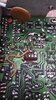
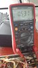
As suggested by Sp5t, I used a 1306 pulled from a Cobra, since the 2166 that was installed mostly its fake..so far I got a stable 50ma with the 1306, (0.900 amp at the DC connector)..also you see that square bias diode? it was there installed and it doesnt look like a diode to me, so I also pulled out a bias diode from the same Cobra..if you examine closely the top board pic, theres something not right, lol..will make you guys scramble for the schematic!..
do you think its safe to install a 1945 now? I have that and a mrf477, but I wouldnt want to risk the 477 until it safe..
Nomad, thanks a lot..and also to Sp5st..
As suggested by Sp5t, I used a 1306 pulled from a Cobra, since the 2166 that was installed mostly its fake..so far I got a stable 50ma with the 1306, (0.900 amp at the DC connector)..also you see that square bias diode? it was there installed and it doesnt look like a diode to me, so I also pulled out a bias diode from the same Cobra..if you examine closely the top board pic, theres something not right, lol..will make you guys scramble for the schematic!..
do you think its safe to install a 1945 now? I have that and a mrf477, but I wouldnt want to risk the 477 until it safe..
Attachments
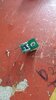
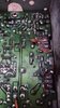
A lot of times those pot when they "Cook" like that, the moment you move them off the position- they will never return to the same resistive value at the position - at least not without some serious rework.
So you know, this board suffered from what HR2510's do, that "self-oscillation" - that discoloration - this thing was powered up and cooked for a while.
Both the 5010 and the 2510 - suffered from this.
Glad you got it fixed.
Just remember the MRF 477 pin out is BEC, not BCE - the Emitter is in the middle and the tab is grounded.
Their fix was to use two 560pF (Series J) to make it "non-resonant" but to help save that radio from more destruction is to installed the NFB that the 2510 used for it's 2166...
But on the 2600 - from Uniden/President - they also added a 33pF from C117 (Output of First Toroid) BACK to the Base of the MRF477. Whether this solved the problem or not - try to see. once you have it working again to help with the self-resonance issue.
Here's what I'm talking about...
I see..I wonder what would happen long term with R258( 330ohm) at the NFB..mine was open, I had to use a 380 ohm because I dont have a 330 at hand right now..
well the saga goes on..the 1945 is fake too lol..wasnt getting power..installed that to a tester midland no dice either..so just out of curiosity I installed a 1237 to the Emp and got 2 watts right off the bat..But current at the test point kept rising also from 0.25 to 1.7 and rising..I know that the 1237 is not a proper final in fact its supposed to be a driver..funny thing that although that kept rising, the 1306 driver is rock stable at 0.50..my theory is that this radio doesnt accept anything else than a true 477..which I have 1 but Im going to die if I install it and current rises..wish I had a current stop auto switch..
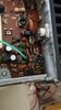
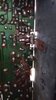
Continuity checks to the GROUND in that area check ok?
I've seen foils open due to it locating a strong RF current path - and by the look of the board that loop - now open - is causing the rise in current.
I've seen foils open due to it locating a strong RF current path - and by the look of the board that loop - now open - is causing the rise in current.
dxChat
- No one is chatting at the moment.