• You can now help support WorldwideDX when you shop on Amazon at no additional cost to you! Simply follow this Shop on Amazon link first and a portion of any purchase is sent to WorldwideDX to help with site costs.

End Fed 1/2 Wave Vertical

RickC.

Hopeless antenna junkie
Mar 30, 2009
400
8
28
Alabama
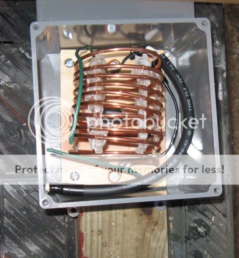
I've been mulling over the idea of a voltage fed vertical for a while now, and finally got one up for 20 meters yesterday. At 0003, so the contest had just ended and the band was suddenly quiet.

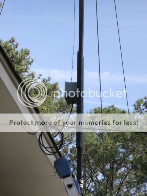
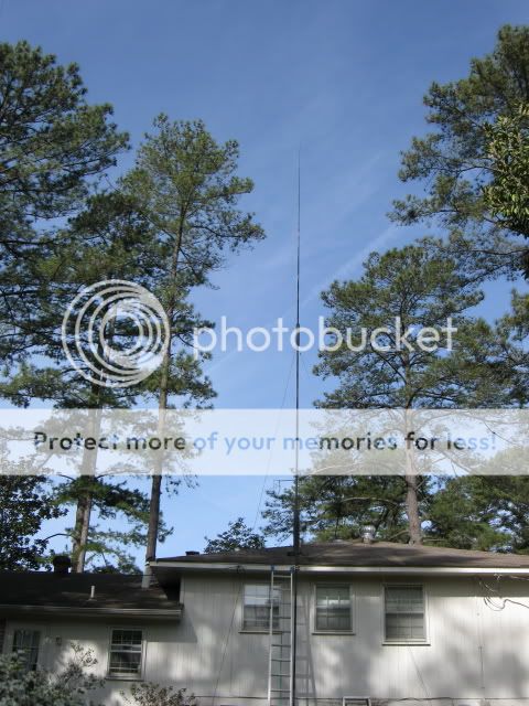
Why a voltage fed antenna? Ah, dunno, just never had built one, thought I'd try it. Feedpoint is 16 ft off the ground, top of antenna is just over 49 feet. Wooden mast, 20 foot crappie pole. Black gold, Texas tea...

20 is in its usual crummy shape today so there's not much of a basis for comparison to a nearby dipole at 30', but my main reason for building this was to see how the expected lower angle of radiation would compare to the 2 element yagi at 35' it replaced.

Impressions so far:

1. No RF in the shack at 600W.
2. Having an .05 wavelength "counterpoise" makes no noticeable difference in RF in the shack or in tuning.
3. With what DX signals are available, the vertical is averaging 2-3 S units better on receive than the dipole (I am not comparing signals that are in the dipole's nulls, the difference there is pretty dramatic, as you would expect).
4. On some signals, there is no difference, and only one one of about 25 has the dipole beaten the vertical-- but it will probably win more when the band is in better shape.
5. Too early to tell how the angle will work out in exchange for the low yagi, but I was unable to break a pileup to a 9K this morning. I'd like to think the beam would have given me a better fighting chance, but since I don't have room for both of them at the same time, I'll never know.

Most of the voltage fed antennas I've known have been low band ground mounted verticals or Bobtails. It could be that few people build these for the higher bands becuase they're more trouble than they're worth. Guess we'll see.


Rick
 

Yep-- now these aren't pretty, but:

I figured a tapped LC circuit would need somewhere around 6.5 uH and 20 pF, and since RG-8 has 30 pF/foot a 10" length or so would work for the capacitor. An online calculator showed an air-wound coil with 10 turns in 4" with a 2.5 in diameter would be about 10 uH, so I figured I should be able to find a tap on that someplace to match 50 ohms at 14.175.

So I bought 10 feet of #8 bare copper at Home Depot, and started looking around the garage for something close to 2.5 inches... All the pint paint cans and spray paint cans have that lip on them, so I ended up using a white vinegar bottle, the plan being to hold the turns in place with epoxy. That turned out to be not such an easy thing, so this is what I came up with for that:

IMG_0306_640x480.jpg


The 1 minute epoxy ran more than I thought so it's not very neat-looking, but it worked:

IMG_0311_640x480.jpg


The coax capacitor was just soldered across the coil:

IMG_0316_640x480.jpg


Test setup with the noise bridge and VSWR meter, using a 4.7K resistor across the coil. 3rd turn on the coil and about 2 1/2" trimmed off the coax made for a near perfect match (whether it would really match the end of a 1/2 wave remained to be seen):

IMG_0317_640x480.jpg


I picked up a 6x6 inch weatherproof junction box while at Home Depot to mount the matching network in:

box1_640x480.jpg


Long story short, I didn't have to change a thing when I got it connected to the actual antenna. I cut the antenna 1" short to compensate for the lead between the coil and the antenna (and as a SWAG for the velocity factor of the insulated wire), and that helped a bit as the antenna favors the low end of the band but is still under 1.5:1 at 14.350.

This is the feedpoint with eveything mounted- that coil of coax is the CATV feed:

feed.jpg


So there's the whole thing:

vertzepp2.jpg


I figured if it didn't work I'd remove the matching network and use a 1/4 wave section of open wire, maybe even make it a J-pole since it was 16 feet to the ground. The mast is just spliced-together 16' sections of 2x2 that were made from ripping a 16' 2x4.

The key word here was cheap, and I nearly pulled the trigger on ordering a 4BTV, but decided to try this first since I'd only be out a few bucks if I didn't like it.

Hope that wasn't overkill.


Rick
 
Nice pics and details. On that matching section, are the green wires where you attach to the feedline or is that going to the vertical section and radials?
 
Hey thanks-- I've seen some guys use that epoxy trick and make coils you'd swear were commercial stock. I couldn't quite pull that off, I'm afraid.

Yeah, those green wires are what attached the coil to the antenna and to the ground lug. I had some 8x32 hardware in the garage and used that and spade lugs for those connections as well as the antenna wire, which is just 14 ga stranded insulated house wire.

The coax was just soldered directly to the coil and the common ground connection. If I had it to do over again I'd use a piece of a buss bar where the coil, coax shield, coax capactor shield, and green wire for the "ground" connect. All I have is a 250W gun and even though those were added one at a time it took forever to heat that up once it was all connected. That coil, 33 feet of wire, and 70 feet of coax make a very good heat sink! There are no radials.

A ground plane would have been much easier to make, could have been multiband, and I could have used the push-up pole that was already there-- but I wanted to avoid the multiple tie-off points, and for some reason was just Jones'n to make one of these. If the band will cooperate I can decide whether I like it.

Rick
 
Makes you feel good when something works, doesn't it? May not be the absolute 'cutting edge' of the latest materials known to man, but who cares? It works.
- 'Doc


...now, if you could just get it above those pine trees... ;)
 
Ha! Yeah, this one almost would earn me a degree in the Crude Arts. Man, some of those pine trees are 150 feet tall!

One of them supports one end of my multiband dipole, using a 3/8" rope and pulleys that terminates into a ground-anchored screen door spring hidden in the azaleas. Several mornings after storms I have expected to walk out and find that antenna gone, but it's survived four years of some pretty strong winds so far.

Rick
 
Last edited:
That looks great to me. I love tinkering with these do-it-yourselfer antennas, and get why you were just "Jones'n" to make one.

Way to go!
 
Rick,
Very nice, keep us updated how that worked out for you. I decided i need a vert. but haven't decided on which one. Leaning towards a 5 btv already have a gap titan but haven't used it since it is very picky on 75/80 (capacitor).
 
Overlord, eh? Ha! I like it...

I will, and thanks. Results so far have been encouraging, but the band remains absolute crap. All I can hear today are stateside stations that can't hear each other, but--

For what this is worth, I received a 20/9 report from a J73 on this vertical, and a 10/9 from an LZ1- both were too busy for me to switch back and forth to the dipole, but the LZ was off the ends of it anyway. 20/9 in the Caribbean from the SE U.S. is nice to hear (he was S7-8 here), but I'd hope to have a decent signal there. Over S9 in Bulgaria was more interesting since he was S7 here (Alabama), but two contacts and anectdotal observations do not prove much. On receiving stateside stations, it's about 70/30 in favor of the vertical, but the W7s and W6s that are clearly better on the vertical are in the dipole's nulls.

The sunspot gods need to show us all some love. Then I'll have a better idea of how this wire performs.

I've heard lots of good things about the Hustler verticals. From what I've read, the curve on 75/80 is a little more broad than many commercial verticals, but not by all that much. I'd still pick it over the HyGain if I were going to buy a trap vertical (which I still may at some point).


Rick
 
Rick,
Thanks for the additional update. Actually it was "Darkrfoverlord" somehow when they transitioned from the old forum the dark somehow was dropped. It was a nickname because a bunch of my 11mtr. freinds would try to get me to come over to the darkside. Hi Hi
 
This is what it is all about. Good stuff. I am more impressed with home made stuff out of what you find laying around than I am with a big store bought beam and tower.
 
Well thanks-- I'm going to have to go to Plan B with this one though. It won't happen today since it's pouring rain here, but the VSWR went nuts yesterday suddenly and the antenna went deaf. Got up on the roof, checked the external connections, yep, all good. Opened the box... black charred plastic and pieces of coax insulation, melted foam in the end of the coax capacitor that had been sealed with RTV and wrapped with several layers of electrical tape. Nothing touching or shorting-- apparently the foam dielectric of the coax capacitor can't handle the voltage. I was afraid that may happen, but figured I wouldn't know unless I tried. It probably would have been fine with 100 watts, but this is 20 meters we're talking about...

Couple of things I could do (well, three):

1. Replace the capacitor with a high voltage variable capacitor.
2. Replace the capacitor with a length of poly dielectric RG-213 or similar.
3. Ditch the voltage feed altogether and use a 1/4 wave matching section of open wire feedline.

I'll go with option 3 since I don't have a transmitting variable on hand (and they're not cheap if you have to buy them new), and since I don't have any poly dielectric coax I'm willing to sacrifice. I don't know yet whether I'll make this a vertical Zepp or a J-pole, but I'll cut up some PVC and break out some wire I have on hand and make that 1/4 wave section today in the garage.

Oh well, it was a nice 6 days with this antenna, and from what I can tell an elevated end fed 1/2 wave can be pretty effective. The notes I kept on A/B comparison show the vertical winning over the dipole most of the time. I still was not able to break either pileup to Kuwait, but those were pretty serious pileups that the 2 el yagi may not have been able to crack either. But the wire's staying where it is, and I'll figure out another way to feed it and report back here.

Interesting experiment.


Rick
 
Last edited:
FWIW poly dielectric RG-213 works up to 40 kv. Last summer I rented a hi-pot tester and that's what was on the output.
 

dxChat
Help Users
  • No one is chatting at the moment.