• You can now help support WorldwideDX when you shop on Amazon at no additional cost to you! Simply follow this Shop on Amazon link first and a portion of any purchase is sent to WorldwideDX to help with site costs.

EPT360010A - Saturn SSB

TR23:
Base = 7.59v
Collector = 0v
Emitter = 0v

How would I test the mode switch?
Follow am flow off control on schematic to where it connects to board, check at that point, like we did with the volume control and mic gain control? Stupid question I know, just tired and worn out. Eyes are burning...

Thank you guys so much, I truly appreciate all the advice. Still gonna yank d23, 24 and 25 out again and try some more new ones.
 
Not sure if you checked already, dont see nothing about that in previous posts, but have that model an FL1 455Khz Filter? did you checked? that filter can kill your AM and FM RX audio if going bad.
 
Replaced that at the beginning of this journey.the old one looked as someone had been jabbing the top with a hot solder tip. Replaced it for safe measures due to looks of it.

Forgot to mention FM receive is fine also.
Thank you though.
 
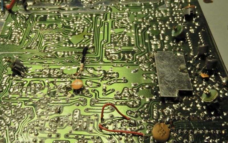
Can you supply a better photo of the areas you circled?

Reasoning - when the AM mode is engaged, the IF doesn't stop - the line from the SSB side - still can produce a signal that swamps out AM - so the issue may not be the detector diodes directly - but thru the RF switch used to kill the IF present on the line when the AM system is detecting.

1673655504218.png

When you switch to AM mode two things are happening - 1st the TR23 is tuning on grounding your detector diodes to make the detector work.

But is the AF detected - able to get thru to the AF preamp?

But the IF signal present is needing to be switched off - so they apply 8V to a bias line and that Diode I see - but need a better photo of, that diode may be the one you're having issues with that needs replacing - the diodes BANDED end goes to ground - that is your RF switch to turn off the IF present so the AM detected signal can pass thru.

If you can bear some more ramblings...

One of many conditions I see in these older radios are when the caps that are in the PICO-farads - even the small stuff, can blow and fail on you - even to the point where - can it even be measured?

So what I've done is simply test lead the ohmmeter to the V x 20 setting and see if the AF preamp is getting proper bias - if it's over 3V on the base - you might have a leaky cap - easier to just replace these up to the AF preamp so you can sleep better at night.

Sometimes the bias is spot on, so what else can go wrong - the RF switch? Maybe - it's been known - but then too, caps can fail open and leaky and you'd not know it until you replace it. Same applies to the diodes use to steer current - but you'd also see that affecting the AF preamps bias from too much signal or too much bias - either way - it pinches off the amp - no audio can get amped.
 
Last edited:
  • Like
Reactions: TM86
More than once I have seen C19 go bad on this board. It's a quick test, just touch the leads of a good cap onto the solder pads for C19. If the AM receive volume jumps up, that cap has lost its effectiveness. It's a 10uf electrolytic.

And if you hear no difference, C19 is not causing the problem.

This assumes that L3 and L4 are peaked properly.

73
 
  • Like
Reactions: Hawkeye351
I've about had it with this thang.

Replaced ALL (every single one) electrolytics.
Replaced D15, D16, D23, D24, D25.
Replaced 455 filter.
Checked TR23 and TR17.
Replaced RF gain control.
Replaced volume control.
Replaced mic gain control.
Replaced 7222ap IC.
Replaced 8v reg.
Replaced AF reg.
Replaced passthrough reg.
All voltages on all ICs are within range.
Realigned 4 times.

Every time, both sidebands, FM and CW receive is fine, only AM is dead. Transmit is great on all modes, even on AM.

Owner is getting pushy, putting pressure on me. It's got sentimental value to him. I did everything I can, I don't know what else it could be.
 
D1 checks good
D2 checks good
D15 checks good
D16 checks good
D23 checks good
D24 checks good
D25 checks good
Tr17 voltages right
Tr23 voltages right
Tr9 voltages right
Replaced FL2 also
Replaced C19, C20 also

Aggravated with this thang.
All solder joints touched up.
Nothing seems wrong, but still weak receive.

Checking D27 now.

How do I test the mode control?
 
Didn't think to ask if any of the skinny tuning slugs show a peak with the end of the slug DEAD EVEN with the rim of the hole?

That position of the slug is the max-inductance setting of the coil. A slug that seems to peak at this position probably is not resonant. It just reached its physical end of travel. The inductance decreases if you continue to turn the slug counterclockwise so that it protrudes above the rim. Appears to be a "peak" but it isn't resonance. And that's what you need to make that stage of the receiver perform its part of the picture.

The maxed-out slug is caused by failure of a capacitor built into the can. A failed cap boots the coil's resonant frequency a lot higher than it should be. Maxing the slug setting will only partway compensate. In general a fixed ceramic disc cap can be soldered onto the two pins where the internal cap was wired. But only if you know the original cap's value. The capacitance value of that internal cap is never revealed in service data. Our second-best solution is to solder a trimmer cap in place, turn the slug a turn or three down into the hole, and set the trimmer cap for a peak. The capacitance you'll need depends on the frequency of the circuit.

I have had radios with seven of these failed internal caps. This radio only needed six. Two of them are brown, and not terribly visible.

ZEVOhR.jpg


73
 
L10 is topped out (any lower and receive drops out).
L14 is topped out (any lower and receive drops out).
L43 is topped out (any lower and RF output drops).
L44 is topped out (any lower and RF output drops).
 
Replaced L43 and L44 with fresh ones with same part numbers. After realigning that stage, I gained 5 more watts. None in that stage is topping out flush to the top now, they're all about 2 to 3 turns below top is where they peak.

Replaced L10 with a fresh one with same part number. Helped out some but not much. Not flush with top now, about 2 turns below top is where it peaks.

Can't find the exact part number for L14 (2009). Could I use a 2008 or 2010 instead?

All this trouble, only to end up with it being the cans the whole time.
 
Last edited:
  • Like
Reactions: 999
That is what this forum is good for... advice from those with more experience and knowledge than you (or I) have. Some of the guys here a much smarter with radios them I could ever hope to be, and I can't thank them enough for sharing what they have learned with the community.
 
They've helped me out tremendously. I love working on these things, it's all I got, but with the help and patience these guys bring to the table makes it even more fun, plus the valuable knowledge they share helps me better myself. I can't thank these guys enough for the wealth of info I've gathered by their help, I'm truly grateful to all on this site.
 
  • Like
Reactions: Handy Andy
The 2009 is sufficiently different from the other types that subbing it probably won't work properly. The trimmer cap patch should work.

A a trimmer cap across the outer two pads of the side with three pins will probably put it back into resonance. If the trimmer's capacitance value is too small, it will appear to peak the receiver signal with the cap at its full-capacitance max setting. I would try a 50pf trimcap to start.

One of these days somebody (else) needs to figure out the capacitance value of all the internal caps in these slug-tuned cans.

73
 
Last edited:

dxChat
Help Users
  • No one is chatting at the moment.