• You can now help support WorldwideDX when you shop on Amazon at no additional cost to you! Simply follow this Shop on Amazon link first and a portion of any purchase is sent to WorldwideDX to help with site costs.

Full wave 11m horizontal co-phased antennas

KF5FUR

Member
Mar 28, 2010
67
1
16
40
Republic of Texas
Google search and images searches have nothing on it. I wonder if it would work well to shoot skip in two directions.

10 & 11 meter full wave co-phased horizontal dipoles (revised size for WWRForums).jpg

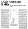
sorry for the weird resolution on the pic, I had to resize it for the forums liking, hope you can read it all.

-Bill
 

Hey,

Since you can't tell the tone of someone from words on a screen and I didn't want to seem like I was running down the idea (I'm not), I didn't comment, but--

What are you after with full wave elements? Half wave end-fed elements I could understand (though center fed would be much easier to feed), but that won't be a good match to 50 ohm coax.

Are you thinking something along the lines of a reversible ZL special or something? Is the 10' spacing something you just decided on, or is there some specific thing you want to try with that?


Rick
 
Bill: I not getting the feed point....are these end feed?...or am I missing something?
#8 awg stranded...wow...2KW++++....
I am running legal limit on my 80m Delta Loop with #12
All the Best
BJ
 
Hey,

Since you can't tell the tone of someone from words on a screen and I didn't want to seem like I was running down the idea (I'm not), I didn't comment, but--

What are you after with full wave elements? Half wave end-fed elements I could understand (though center fed would be much easier to feed), but that won't be a good match to 50 ohm coax.

Are you thinking something along the lines of a reversible ZL special or something? Is the 10' spacing something you just decided on, or is there some specific thing you want to try with that?


Rick


I haven't heard of "reversible ZL special" what is that Rick?
Well I didn't put the feed point on the sketch because I wasn't sure of it, being co-phased in all. But I figured (possibly out of ignorance) that a full wave might me better than say a 1/2 wave, I really don't have anything to back that up, but I am here to learn and please correct me if I am wrong.
Also I was thinking that the ideal spacing would be 9-10 feet, again correct me if I am wrong. I could definitely go with center fed 1/2 wave elements.
I am just in the very beginning of my planning my homemade 10m/11m base antenna. So any input critical or not is very welcome.

-Bill
 
Co phased 1/4 wl would be easiest to make work as far as input impedance.

A Lazy H oriented vertical would achieve what you are looking for as far as a bi directional pattern but it is not steerable.

sounds like you have some good ideas, and it is a lot of fun experimenting.

Max gain will probably be with .625 wl spacing between elements.

How do you plan on mounting the antennas?
 
Last edited:
Co phased 1/4 wl would be easiest to make work as far as input impedance.

A Lazy H oriented vertical would achieve what you are looking for as far as a bi directional pattern but it is not steerable.

sounds like you have some good ideas, and it is a lot of fun experimenting.

Max gain will probably be with .625 wl spacing between elements.

How do you plan on mounting the antennas?


Well it looks as though a lazy H setup would work with the mounts shown in the sketch I drew. But moving the mounts closer obviously and attaching them to a couple of cinder block racks that ride the hip on the roof. Stretch a couple of cords between the wood rods to support the antenna elements and presto. Thanks for the idea waverider!

150220.gif

This looks similar to what I've drawn

But something similar to this one I could rotate it only 180 degrees for 360 degree coverage.

Colinear revised size for WWRForums.png

Or just string the Lazy H up between a similar looking frame, cool, thanks again for the idea.
 
A Lazy H oriented vertical would achieve what you are looking for as far as a bi directional pattern but it is not steerable. How do you plan on mounting the antennas?

Or like this connected to a rotator, and squared U frame with the Lazy H hung inside it. I had to recreate this pic from a Google images search, so I am not taking credit for the antenna design itself.

Lazy H cell pic recreation.gif
 
Your welcome on suggestions.

If you have a small rotor, and want a decent gain light weight yagi.

I really like Moxon antennas, they work and work well for a couple pieces of wire.
 
Your welcome on suggestions.

If you have a small rotor, and want a decent gain light weight yagi.

I really like Moxon antennas, they work and work well for a couple pieces of wire.

I have an 2 old channel master rotators, one from the 90's that is still made by Radio Shack and an older one that is from the 70's that mounts the rotated pole through the unit, it seems a lot more stable than the one that has the mount out of the top, in fact it lurches to the side every time it moves, piece of crap for anything not light and with a low wind load rating. The older one works with the Channel Master style R. Shack box. Don't know how much longer all that will last, I wonder if the motors have brushes, anyone know? They are all worm gear setups so maybe they are brushless motors.
 
It all boils down to where the antenna's radiation pattern puts/hears a signal. There's no particular benefit by making the thing a full wave length unless the signal gets to where you want it. I haven't modeled such a thing, so can't/won't make many guesses about it. Typically, 'longer' antennas have multiple 'lobes' and one of them may be in a useful direction. How do you tell? You've got two choices, really. Try it and see, or model it and see. (Or find some one who's already done it??)
If you thing that might be fun, why not?
- 'Doc
 

dxChat
Help Users
  • No one is chatting at the moment.
  • dxBot:
    Tucker442 has left the room.
  • @ BJ radionut:
    LIVE 10:00 AM EST :cool:
  • @ Charles Edwards:
    I'm looking for factory settings 1 through 59 for a AT 5555 n2 or AT500 M2 I only wrote down half the values feel like a idiot I need help will be appreciated