• You can now help support WorldwideDX when you shop on Amazon at no additional cost to you! Simply follow this Shop on Amazon link first and a portion of any purchase is sent to WorldwideDX to help with site costs.

gainmaster vs i10k a quick test with locals

if only we could have no mast and feedline in the real world, cheaper better lol,
the problem is even if you isolate the mast you still have feedline, w8ji says a choke or similar won't work unless you add radials, which eliminates the no radials isolated mast from the race leaving isolated mast + choked feedline + radials as the best of a bad bunch:eek:
 
Dave, the yellow does not show up well so whatever model ends up as yellow, I run it again...and it shows up as red. I do this just so the line is easier to see. So you're right, the red and yellow are the same model in this case. I wish I could change the colors and/or the width of the lines to help make this function look better, but we can't.

The black line is noted in the descriptor list as *Primary. The Primary pattern is the model that is open and being displayed at the time. The other patterns are overlaid on top. The title for the Primary is noted below the pattern, so in this case it is, "Imax 40' no GPK mast isolated."

It looks like to me the Imax with no GPK, and with an isolated mast is the best pattern among these models, and it is marked in black. The dark blue is next, but there is no mast. So Bob is right about the isolated mast, but I'm not sure about the need for the GPK. It looks like the GPK tends to kick the max lobe skyward in all cases.

I see i understand now thanks
 
i think the 1/2wave mast and coax to ground that me and my local are using is one of those worst case lengths w8ji talks about, i read somewhere that the coax or mast need only be resting on the ground,

Common mode current
 
if only we could have no mast and feedline in the real world, cheaper better lol,
the problem is even if you isolate the mast you still have feedline, w8ji says a choke or similar won't work unless you add radials, which eliminates the no radials isolated mast from the race leaving isolated mast + choked feedline + radials as the best of a bad bunch:eek:


I tend to agree with you this is the best way to help minimize CMC.

i think the 1/2wave mast and coax to ground that me and my local are using is one of those worst case lengths w8ji talks about, i read somewhere that the coax or mast need only be resting on the ground,

Common mode current

Bob, I could be wrong, but I think this could be meaningful for consideration.

I'm sure you've seen and read the article below, written by W8JI. You might also recall our discussion back in 2010, where I proposed an idea base on this article. That idea suggested that maybe we could mitigate CMC on our antenna mast and feed line...simply by using some particularly suitable mast height and feed line length to the ground if we could determine what that length was.

The other day I posted a comment suggesting my Eznec5 modeling efforts indicated that the magnitude of CM currents seemed to vary along the mast in a sinuous curve rather than linear and, among other things, that was due to changes in height. I also noted that modeling indicated this at very small differences in height. This is not all there is to the issue, but IMO the following pdf file is in response to your comments above. I also think this might tend to agrees with what W8JI suggested below.

I used a portion of another modeling project where I compared a full 1/4 wave radiator vs. 1/4 wave that was shortened with a large Top Hat. In this case I selected the model that was a 1/4 wave resonant ground plan at 40' feet to support my point. I adjusted this model to 17' - 19' feet for your consideration. The purpose for my choosing these models was to see the affects of height on matching as well, and using a resonant antenna that matched to some numbers that we might expect, thinking that would be helpful in understanding.

I-Max 2000 Solarcon A-99 Antenna
The following model is an I-Max 2000 5/8th wave vertical with a vertical feedline or mast connected to the antenna base, and no radials. In this case I picked one of many worse-case feedline or mast lengths:
end-fe15.gif


Feedline shield current is 100% of antenna current. This illustrates why some users complain about SWR problems and RF in the shack with end-fed verticals like the I-MAX 2000, while other people do not complain and seem to love the antenna. This is because some people pick a lucky mast height or feedline length, while others are not so lucky. Unlucky people happened to choose a mast height, feedline length, or grounding system length that enhanced common mode problems.

Take note of the current magnitudes indicated in red at different heights, and the affects this has on the patterns. I was really amazed at what 19' & 20' feet showed. Sorry I forgot to include 20' feet in the pdf, but it was the worst of all.

View attachment Bob's .50 wave mount.pdf

By the way Bob, I agree that laying the coax on the ground will help minimize CMC into the shack, but they will still radiate from the feed line as it hangs from the antenna, and the feed line can still remain a problem.
 
eddie, im pretty sure cm impedance is not a linear scale but sinusoidal as you suggest,

are those plots done in freespace or is the mast connected to ground?,
i could be wrong but id expect 1/2wave to ground or multiples thereof to be worst case scenario if the mast feedline comes to ground,
your plots seem to indicate the opposite to what i expected as if the mast is dangling in freespace where id expect 3/4wave or odd 1/4wave multiples to be worst case,

this is what i thought avanti were getting at when they talk about the astroplane mast having a notable effect on takeoff angle if its shorter than 1/2wave or about 8ft below the hoop, but what if your mast is longer?, do ya feel lucky? well do ya :unsure:

we are getting back around to why i don't care much for freespace plots that ignore feedline/mast and ground effects, things can look peachy untill you include them,

i really should learn to use eznec:unsure:
 
eddie, im pretty sure cm impedance is not a linear scale but sinusoidal as you suggest,

are those plots done in freespace or is the mast connected to ground?,
i could be wrong but id expect 1/2wave to ground or multiples thereof to be worst case scenario if the mast feed line comes to ground,
your plots seem to indicate the opposite to what i expected as if the mast is dangling in freespace where id expect 3/4wave or odd 1/4wave multiples to be worst case,

this is what i thought avanti were getting at when they talk about the astroplane mast having a notable effect on takeoff angle if its shorter than 1/2wave or about 8ft below the hoop, but what if your mast is longer?, do ya feel lucky? well do ya :unsure:

we are getting back around to why i don't care much for freespace plots that ignore feedline/mast and ground effects, things can look peachy untill you include them,

i really should learn to use eznec:unsure:

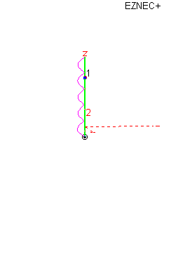
All of these models are set over real Earth as per Eznec5. I set the mast segments at 1' each. They are noted on the Antenna View details as wire #5. Again my intent was to demonstrate the current magnitudes at different heights.

I'll have to refresh my memory about the AP. I have not modeled it as yet. I'm not even sure modeling and changing the mast will show us this trend toward a higher angles, but the guys at Avanti saw something, and they were likely familiar with the math and theory necessary to do what modeling does today.

Regarding free space models and things looking peachy. IMO that is the way free space models are supposed to work...they serve a very important purpose. This idea is very similar to my ideas presented in another thread about gain and the .64 vs. .625 wave. It might be important to understand...if folks could get their thinking past their bias for a minute.

Eznec has a feature called "Average Gain." This feature gives the modeler some idea about the efficiency of his design, and allows one to tweak and check his antenna construction, features, and the affects on losses that we could not determine without a lossless base line model. Again this is similar to what I've been talking about in the other thread regarding .64/.625 wave. As we do things (modify) to make our antenna work over real Earth and show maximum gain and angle, we tend to add loss. Then we tweak striving to minimize those losses, back down toward the free space model and hopefully we increase efficiency in the process.

Considering efficiency, the closer we get our model back toward the free space model the better off we will likely be, even though we can't completely duplicate our free space model or make it as lossless over real Earth. The free space model just gives us a base line to compare the real life model, and that is why we run the Average Gain feature only in free space and with all losses minimized with the model. Bob, it is similar to what you use to do in the open fields of your parents place while testing your antennas.

Bob, albeit there are issues with modeling, I think you would be captivated by learning to model Eznec. I don't know what has blocked your progress in the past, but mine always had to do with a lack of understanding the data entry part. After I saw the light, with simple models, the program became relatively easy to get the hang of it. Then I had to learn what I could about the features, functions, limitations, and controls. I think I bought the upgrade in about a month or so.

You can do it, and whiz past me in nothing flat. It would be great to have someone to collaborate with in learning.
 
im sure i would like nec if i got into understanding how to use it, i would like antenna magus + cst msw even more but it don't have the antennas that interest me in the antenna database and i have no clue how to start from scratch,
my comment on freespace models is not aimed at dismissing your models in any way, if anything your models reinforce what i though the likely outcome so long as its in freespace,
a no radial endfed on a 15-20ft scaffold pole grounded via pole or earth wire is a very common install here,
imho such a setup is crap and prone to rfi, just my observation/experience,
you remember the a99 we isolated and added wire 1/4wave radials to ;)

Bob, I know its been a long time, but I had a thought to model your idea here. I started, but had a thought that I did not have the actual measurements for the bent radials you used. Here is what I've done so far. Maybe you could tell me the length of the two piece radials you used.

Is this MM200's antenna you talked about before? If it is, I would like to know if the models might show to even be close to what you observed back then. I don't expect you'll be able to tell much as far as the actual gain and angles that will result, but I was mostly considering that there might be something show up regarding the TVI issue you mentioned.

These images basically are basically showing the overall look and the dimensions...that are noted in the details. The last two views are overhead views just to see if the antenna looks like MM200's.

View attachment Bob's .50w idea insulated.pdf
 
i was wondering if wj8i is right about the choke not working unless there are radials then why does it work on the gainmaster?
 
the gm is a dipole ( no missing half ) the imax floppystic without radials is endfed (half of an antenna), i think kirchhoff explains it better than i could,

two more locals swapped from imax to gainmaster, neither are mounted high, both guys are very happy with better signals and less noise than their imax,
half time tests score stands at ( gainmaster 5 imax 0 )

the imax's days are numbered in this area.
at lowish mounting heights 15-20ft they seem to do what sirio claim so long as you are not comparing it to a full size radial 5/8wave such as my i10k.

i had to replace my imax because the bottom broke and water was getting in before it layed over to one side so i junked it. it was all hairy and not worth the trouble tof fixing it. my gainmaster is alot quiter and everyone is stronger by at least a sunit. i know its a 5/8 and the i10k is a 5/8 but the i10k is end fed so the bottom is out of phaze. i dont see why the gainmaster wont be better since there both 5/8 but the gainmaster is all in phaze and even fed higher up. i dont see anything majic about a 5/8 with radials even if it is built real well like the i10k
 
i don't see anything majic about the i10k either but it edged out the gainmaster when tested on the same short pole, the imax was well behind,
i have not tested them higher up so i won't speculate.
 
yeah i think you have to get the gainmaster higher off the ground and away from obsticles or it screws up its performance more then the bottom fed types
 

dxChat
Help Users
  • No one is chatting at the moment.