
You are using an out of date browser. It may not display this or other websites correctly.
You should upgrade or use an alternative browser.
You should upgrade or use an alternative browser.
-
You can now help support WorldwideDX when you shop on Amazon at no additional cost to you! Simply follow this Shop on Amazon link first and a portion of any purchase is sent to WorldwideDX to help with site costs.
Galaxy DX-2547 suddenly virtually no output
- Thread starter Adamf
- Start date
Might just need a simple tune up - check your GATE voltages though, make sure that the mA draw at the TP8 and TP 9 from TP7 is no more than 55mA EACH - done as a Ammeter - for mA (Mili-amp) draw.
Remove that jumper board, set up your ammeter for 200mA...
See graphics and photos for which trimmer does what...you have all you need to do this.
Done by NEGATIVE to TP 9 , POSITIVE to TP 7 then NEGATIVE to TP 8 - POSITIVE to TP 7 those trimmers adjust Driver and Final individually.
Done in SSB Mode, no modulation. Put a GOOD dummy load on it.
An easy formula to remember...
1mA is 1/1000 (one one-thousandth) of an Amp so...
1,000mA is 1 Amp
Seems small, but 55mA is all you need for the Driver and Final as IDLE current.
Please - DO NOT set for voltage - ALWAYS set for mA Draw current...

Did anybody else read the title and think “suddenly bad solder joint” or was I alone on that.
Good point, but to elaborate...
When a radio comes in, and has "no output"
What is one of the first things you SHOULD do?
Answered in post #18...
Lift the legs of the power amplifiers and clean underneath them - e.g - clean and verify your work is not causing this condition.
That step is almost a requirement with Silver soldering (Pb-Free) these days - ranks right up there as a Requirement like 10+ year old radios recapping.
The rest of the mess was answered by Voltage readings, changes and operation.
No power? But seemed to operate as expected...
Bad parts blown shorted, usually pulls down the power thru excessive current draw, Radio goes Dim.
... or ...
Blown open parts keeps power too high because there's nothing there to draw it in and use it - no power flow. Radio just sits there and idles.
That is the Why I asked about voltages - no sag, little power - hardly any current draw - open parts or open lines to the parts that would take power and pull down those voltages you need to set for, would show voltage variances (none to little voltage drop) while bad soldering, or shorted parts would show up has heating, or very strong power draw and still low voltages.
So - open - or blown parts leaves higher idle voltages and little power draw
Shorted parts lower expected voltages thru higher current demands dimming displays...
Either way, low or little to no power out...
A short between two stages to ground (blown cap to ground) gives the same thing - both sides just sit there waiting to work - produce a signal. But, one side would produce power - pulling voltages down thru the short until it failed.
So since he had it working to a degree - variable worked - voltages seemed high but not excessive - best to review what was done, do the best you can to clean up the work - then try again.
Remove all doubt...
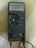
Hi Andy, I will do that tomorrow but I am embarrassed to say when it comes to using the ammeter portion of the meter for some reason I always have trouble. I use an old Fluke 75 DVM (pic attached) and I assume red lead to the 300ma socket, black lead in common socket and set the meter for DA amps, yes? Thanks, turning in now will read tomoorow., Adam
Might just need a simple tune up - check your GATE voltages though, make sure that the mA draw at the TP8 and TP 9 from TP7 is no more than 55mA EACH - done as a Ammeter - for mA (Mili-amp) draw.
Remove that jumper board, set up your ammeter for 200mA...
See graphics and photos for which trimmer does what...you have all you need to do this.
Done by NEGATIVE to TP 9 , POSITIVE to TP 7 then NEGATIVE to TP 8 - POSITIVE to TP 7 those trimmers adjust Driver and Final individually.
Done in SSB Mode, no modulation. Put a GOOD dummy load on it.
An easy formula to remember...
1mA is 1/1000 (one one-thousandth) of an Amp so...
1,000mA is 1 Amp
Seems small, but 55mA is all you need for the Driver and Final as IDLE current.
Please - DO NOT set for voltage - ALWAYS set for mA Draw current...
Attachments

Hi Andy, OK, so I figured out the correct settings for my meter and on the first test measuring TP9 to TP7 and adjusting VR12 the service manual calls for a 50ma setting which was no problem. For the testing between TP8 and TP7 and adjusting VR10 the service manual does call for 100ma but I could not adjust it above 47ma and output still was about 1/2 watt on deadkey when I went back to test on AM so something else is wrong? If you can tell me anything else I can try I am ready. Thanks, Adam
Yes, when it's 47mA you have a problem - or set of them...
Since the Bias can't be set thru DRAW - that means either a Resistor or Diode or both has blown.
Double check the Diodes - look for - and fix shorts - one of the "Zeners" may have blown shorted, or you have a short in the BIAS line pulling DOWN the "Gate trigger" voltage.
Just have to go find it.
This might help
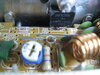
(Found a BAD CRACKED Cap by Driver - might want to fix that...)

Since the Bias can't be set thru DRAW - that means either a Resistor or Diode or both has blown.
Double check the Diodes - look for - and fix shorts - one of the "Zeners" may have blown shorted, or you have a short in the BIAS line pulling DOWN the "Gate trigger" voltage.
Just have to go find it.
This might help
(Found a BAD CRACKED Cap by Driver - might want to fix that...)
Rats Andy, replaced the cap (.047uf/50V) but no luck. Anyway, I will perhaps check a few diodes and resistors, I will ask this last time for your help then take the radio out back and shoot it. For diodes (zeners) etc, forgive me again, best way to check them and which ones are the most likely candidate? After this I will turn in my soldering iron, I wasted too much of your time already. Adam
Just be sure that the Finals Gate mA DRAW can be set.
IF you can't set it, then you simply have to check and repair the parts in the BIAS circuit preventing the Gate voltage from getting set right..
Zeners are finicky. But can and are, checked like any other Diode. Tested both ways of polarity to see if it's shorted, or blown open
The 5.6V types used are 1 Watt rated.
IF the "diode" failed, you can install any diode in there - just make sure the Banded side is to the LEFT (Towards GATE) - the purpose of the Zener is to prevent the GATE from blowing up from too much power from the DRIVER.
Keeping a Zener in there just prevents the Final from getting too much RF Input signal from the Driver.
Just when you do the TP test for "draw" - keep it lower - like around 55mA
I do not recommend 100mA - unless you install something at Cx located back by the Pre-Driver.
Why?
IF you don't - you may wind up having this problem again.
There are some threads about this...
https://www.worldwidedx.com/threads/rci-2995-dx-problem.254336/#post-717647
https://www.worldwidedx.com/threads/dx2547-power-supply-issues.234071/#post-639861
https://www.worldwidedx.com/threads...-and-the-correction.157713/page-2#post-726275
https://www.worldwidedx.com/threads/galaxy-dx-2547-voltage-regulator.258183/#post-734543
https://www.worldwidedx.com/threads/connex-3300hp-power-output-problem.239565/#post-660891
https://www.worldwidedx.com/threads/ranger-2995-dxcf-swr-problems.261022/#post-754044
https://www.worldwidedx.com/threads...driver-bias-voltage.155425/page-3#post-656260
Last edited:
Good point, but to elaborate...
When a radio comes in, and has "no output"
What is one of the first things you SHOULD do?
Answered in post #18...
Lift the legs of the power amplifiers and clean underneath them - e.g - clean and verify your work is not causing this condition.
That step is almost a requirement with Silver soldering (Pb-Free) these days - ranks right up there as a Requirement like 10+ year old radios recapping.
The rest of the mess was answered by Voltage readings, changes and operation.
No power? But seemed to operate as expected...
Bad parts blown shorted, usually pulls down the power thru excessive current draw, Radio goes Dim.
... or ...
Blown open parts keeps power too high because there's nothing there to draw it in and use it - no power flow. Radio just sits there and idles.
That is the Why I asked about voltages - no sag, little power - hardly any current draw - open parts or open lines to the parts that would take power and pull down those voltages you need to set for, would show voltage variances (none to little voltage drop) while bad soldering, or shorted parts would show up has heating, or very strong power draw and still low voltages.
So - open - or blown parts leaves higher idle voltages and little power draw
Shorted parts lower expected voltages thru higher current demands dimming displays...
Either way, low or little to no power out...
A short between two stages to ground (blown cap to ground) gives the same thing - both sides just sit there waiting to work - produce a signal. But, one side would produce power - pulling voltages down thru the short until it failed.
So since he had it working to a degree - variable worked - voltages seemed high but not excessive - best to review what was done, do the best you can to clean up the work - then try again.
Remove all doubt...
But, not trying to go against you here, if you look back to post 1 he says he hadn’t used it for a few weeks. So he turns it on and has the low output issue, he then changed the mosfets and still had the same issue. To me that says that up until he changed the mosfets he hadn’t done any work to it. He just turned it on and it had pooped the bed.
That’s the only reason I said what I said, I didn’t read anything that said any work had been done and then it quit working properly. Just sayin.
That’s the only reason I said what I said, I didn’t read anything that said any work had been done and then it quit working properly. Just sayin.
There are dangers in every scenario, this one is not unique.
We discovered 3 (three) things...
Cracked cap,
Bias not working right
and bad output cap.
Out of those three...
Whether works been done to it or not, @Adamf he admirably - took to the task of attempting to fix his radio.
- What you may have got confused with, is me asking if he's done MOSFET before?
- IF that is the case - my intent was to warn the OP about things that may not look right.
- There are two types of parts that can be used in THAT SAME BOARD - that's our curse.
When previous work has been done to it or not - I work alongside people that share a passion for radio - up to and including keeping this market-hobby-effort alive by trying to repair radios that would otherwise be filling up landfills.
You are seeing some of the success and failures, of Forums versus owning a shop and knowing exactly the condition of the problem and it's solutions - at hand - by being there working on the problem directly.
People make a living off of that.
I also understand that you can get in over your head.
You can also maintain a radio by just repairing that which is broken and the radio will recover.
There are people out there that make fun of our hobby and even how we act out there...
Some people though, don't take it well.
It's not that simple.
In this case, my failures are simple, MOSFET to Bipolar or if the radio quit, (being blunt) directly - no matter what - @Adamf took to the challenge of repairing his own equipment. I'm trying to pick up where he's at and the direction we went, - accelerated pretty fast.
Now, to review, if he only replaced the cap - it may or may not have worked.
The output cap failed, but for that failure can be the Final and or Driver (both really) right along with it.
Bias was low or inadequate - could it have caused the Final to fail - yes, because I've seen radios that seem normal and brand new - fail unexpectedly - power surges onto long winded SSB nets - people don't know what's going on with the radio until it doesn't work anymore.
So what caused it?
I have theories and even posted some possible solutions - but that doesn't fix the radio that's broken
To apply the suggestions for others to use, just might let those other radios last longer - but we still have a radio that whether it's been worked on before or not, there is a user out there determined to fix that which is broken.
So if you're saying He didn't have any work done to it, it didn't matter to me.
- - I'm letting him see My Approach in the repair,
- - MOSFET or Bipolar, there may be a lot of work to do to restore everything back in.,
- - I'm also advising - not trying to have him recreate the problem ...
- I only asked if he had work done to it - not the "he did the work to it" No!
- - did some one work on his radio before this?
- - and after some time using it - it doesn't work...
- The above statements have to be taken seriously, for if it is not followed, replacing parts will only allow the radio to be used for short times before the problem occurs again.
- IF it's due to a poorly done mod, you correct the mod first to make it work right then the radio can survive.
- now you know what has been done,
- replace the output cap,
- fix the broken one,
- keep the final and driver parts from the OEM (not the 520N)
Does the Radio start working right? Maybe maybe not.
- - I am fixing, working - helping someone - taking them at their word - trying to restore something they cherish enough to keep and fix themselves - they already went too far.
IF they want my help, they let me come alongside and work with them - in many ways the effort of communication goes beyond the simple and into pretty complex interactions not normally seen in Twitter or other Social media outlets.
That is the beauty (or curse) of the Forums approach.
Way too easy for someone to come along and take a stalled car and turn it into a twisted wreck.

I'm posting this as a reminder to myself...
Don't take myself too seriously...
Last edited:
Hi Andy, etc...So I put the DX-2547 aside for a while and decide to look at the 2 diodes that are right in front of each mosfet, D90 and D92, the manual shows them as 1N4148 but what is interesting is that the manual and the circuit board clearly show the orientation of the diodes the opposite direct of the way they are installed, On each diode they are installed with the positive band on the LEFT hand side but the board and schematic show the band on the right hand side? Of course the radio came to me that way and worked fine for months. Does this make any sense? Thanks, Adam
Attachments

Yes, the answer lies in this thread - your topic...
There are two posts I want you to consider...
Here's one...
https://www.worldwidedx.com/threads...virtually-no-output.262093/page-2#post-766977
The photo in that one, points to the trimmers.
Here's the other...
https://www.worldwidedx.com/threads...virtually-no-output.262093/page-2#post-766981
Ok, you may have seen them over and over again, but...
You're having a problem adjusting Bias on one of those two MOSFET's.
And...
Knowing you did find 1N4148's in there, helps to bolster my theory on why the radios output did drop.
It was not just the cap - although the cap failed to cause the cascaded failure - the Diodes actually did it.
Why?
IF those are 1N4148's they needed to be ZENERS - not ordinary Diodes.
Because...
PIV - Peak Inverse Voltage - how much Voltage the Diode with direct in one direction when that power is even going in REVERSE - in most 1N4148's it starts at about 50V PIV - a rating and a breakdown.
What happens? Then you apply 50 volts but reverse the leads - The Diode will conduct, doesn't act like a one-way valve anymore - power travels both ways - until too much power in applied wattage (in power) makes the part fail in one of two ways...
In any radio Driver and Final produce power - one needs the other to make the circuit complete and send out a signal.
The Driver produces some power mixed in with audio (AM thru the Mirror Board and AM Regulator) - or a little more power if you are sending a RF signal that really has audio or information on it (SSB Mode)...
Either way, the Driver produces power - in some instances of Peak - over several WATTS of power are sent into the Final.
What is the Diode on the Final Doing? Bearing the brunt of not just the power flowing into the Gate BEHIND the Diode (The Bias circuit) but the RF signal that is present on it's leads GOING INTO the Gate.
IF there is enough Peak to Peak power present - it can destroy the GATE before it blows the DIODE.
Gates are rates by Peak to Peak voltage that can be applied - usually (with the IRF520) 20 volts Positive and 20 Volts negative - a RATING. It's a value, not cast in stone - not always perfect, so if you even get close to the 40 volt "Window" the Final can operate in - you can still blow the Final - and everything stops - yet all the parts in the strip seem ok - just looking back at you - like nothing went wrong.
Note that 40 volts and 50 volts - are close but not the same number - there's a 20% INCREASE you have to arrive to to get up there before the Diode will reverse it's directionality and exhibit PIV. But - it's too much for the MOSFET to withstand.
This is why they use ZENERS, to keep the event from occurring in the first place.

So for Galaxy, they use 5.6V 1 Watt rated parts - but if you sub in a STANDARD Diode - yes, the Diode works but does not provide the protection the ZENER will, keeping the power in the Gates RATED voltage range (when supporting parts are incorporated correctly) to let your radio last longer.
The 5.6V means that the Zener can be installed as a protection device - put in with it's polarity reversed - reversed from an ordinary diode from the Bipolar days - to provide a means to LIMIT peaks.

There is an inherited trait of several faults using Zeners have, over ordinary diodes - one being the QUALITY of signal that can be passed into the GATE.
Zeners, when installed reversed like shown in the links above, they will "conduct" and pull down the power it "sees" at it's banded end (cathode) - this means not just voltage - EVERYTHING present - like it clamps it. This can make for some strange results if you're not careful.
I could go on, but I'll let you digest this...
There are two posts I want you to consider...
Here's one...
https://www.worldwidedx.com/threads...virtually-no-output.262093/page-2#post-766977
The photo in that one, points to the trimmers.
Here's the other...
https://www.worldwidedx.com/threads...virtually-no-output.262093/page-2#post-766981
Ok, you may have seen them over and over again, but...
You're having a problem adjusting Bias on one of those two MOSFET's.
And...
Knowing you did find 1N4148's in there, helps to bolster my theory on why the radios output did drop.
It was not just the cap - although the cap failed to cause the cascaded failure - the Diodes actually did it.
Why?
IF those are 1N4148's they needed to be ZENERS - not ordinary Diodes.
Because...
PIV - Peak Inverse Voltage - how much Voltage the Diode with direct in one direction when that power is even going in REVERSE - in most 1N4148's it starts at about 50V PIV - a rating and a breakdown.
What happens? Then you apply 50 volts but reverse the leads - The Diode will conduct, doesn't act like a one-way valve anymore - power travels both ways - until too much power in applied wattage (in power) makes the part fail in one of two ways...
- A Molten Pellet - melted junction causing a dead short
- A popped Pellet - the part opens explosively and breaks the circuit - open line like a blown fuse.
- IN the meantime - the DIODE acts like a dead short until it or something else in the circuit feed - blows open to stop the process.
In any radio Driver and Final produce power - one needs the other to make the circuit complete and send out a signal.
The Driver produces some power mixed in with audio (AM thru the Mirror Board and AM Regulator) - or a little more power if you are sending a RF signal that really has audio or information on it (SSB Mode)...
Either way, the Driver produces power - in some instances of Peak - over several WATTS of power are sent into the Final.
What is the Diode on the Final Doing? Bearing the brunt of not just the power flowing into the Gate BEHIND the Diode (The Bias circuit) but the RF signal that is present on it's leads GOING INTO the Gate.
IF there is enough Peak to Peak power present - it can destroy the GATE before it blows the DIODE.
Gates are rates by Peak to Peak voltage that can be applied - usually (with the IRF520) 20 volts Positive and 20 Volts negative - a RATING. It's a value, not cast in stone - not always perfect, so if you even get close to the 40 volt "Window" the Final can operate in - you can still blow the Final - and everything stops - yet all the parts in the strip seem ok - just looking back at you - like nothing went wrong.
Note that 40 volts and 50 volts - are close but not the same number - there's a 20% INCREASE you have to arrive to to get up there before the Diode will reverse it's directionality and exhibit PIV. But - it's too much for the MOSFET to withstand.
This is why they use ZENERS, to keep the event from occurring in the first place.
So for Galaxy, they use 5.6V 1 Watt rated parts - but if you sub in a STANDARD Diode - yes, the Diode works but does not provide the protection the ZENER will, keeping the power in the Gates RATED voltage range (when supporting parts are incorporated correctly) to let your radio last longer.
The 5.6V means that the Zener can be installed as a protection device - put in with it's polarity reversed - reversed from an ordinary diode from the Bipolar days - to provide a means to LIMIT peaks.
There is an inherited trait of several faults using Zeners have, over ordinary diodes - one being the QUALITY of signal that can be passed into the GATE.
Zeners, when installed reversed like shown in the links above, they will "conduct" and pull down the power it "sees" at it's banded end (cathode) - this means not just voltage - EVERYTHING present - like it clamps it. This can make for some strange results if you're not careful.
I could go on, but I'll let you digest this...
Last edited:
dxChat
- No one is chatting at the moment.