I picked up a nice galaxy Saturn but it has no transmit output power. The TX light comes on and I can hear sound thru another radio when I key up Saturn but no watt meter reading at all. The receive seems to work fine except I have to turn volume up to at least midway setting to get decent sound. The meter on radio also not working on transmit but if some one close works on receive. Any ideas. I cannot find any info on how to check finals like voltage chart.

You are using an out of date browser. It may not display this or other websites correctly.
You should upgrade or use an alternative browser.
You should upgrade or use an alternative browser.
-
You can now help support WorldwideDX when you shop on Amazon at no additional cost to you! Simply follow this Shop on Amazon link first and a portion of any purchase is sent to WorldwideDX to help with site costs.
-
A Winner has been chosen for the 2026 July 4th Retevis RA89R Giveaway! Click Here to see who won!
Galaxy Saturn no transmit power.
- Thread starter Jimbo165
- Start date
Meter doesn't show output? Small surprise if the radio doesn't have output. Probably the final output transistor(s) blown if there was no a no load/shorted output condition. You may have to replace the final(s).
If you do not do any testing beyond what you have found; then you cannot know for sure. Simple as that.
If you do not do any testing beyond what you have found; then you cannot know for sure. Simple as that.
I was hoping that I could test finals in radio without removing them but do not know what voltages and location on final.
Not really possible to test in circuit.I was hoping that I could test finals in radio without removing them but do not know what voltages and location on final.
Wow, sure sounds like one of the original 1989-era five-band radios.
How many bands are on yours? This will narrow down the age.
The oldest Saturn models will tend to have the longest laundry list of faults when they get past the 20-year mark.
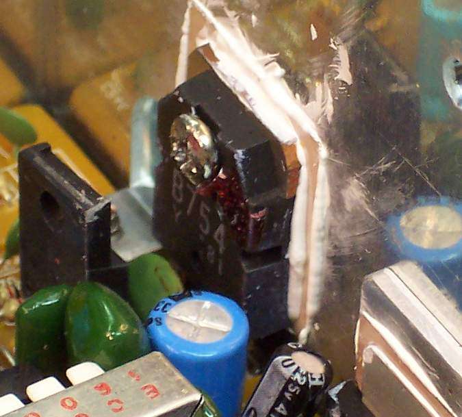
Once it's old enough to buy a drink, we see a lot of them with toasted final transistors. The final transistors' metal tabs that bolt to the aluminum heat sink will be a dark, flat black color. This is the metal oxides that build up from excess heat. The habit back then was to "turn up" the bias adjustments, and cause excessive heat to cause the two finals and sometimes the driver transistor to fail.
The added current load to the final transistors has to pass through the modulator transistor. Some folks like to call it a "regulator", since it also controls the radio's carrier power in AM mode. This is what it looks like. Frequently the factory would leave off the white heat-conducting compound that fill heat-blocking gaps under the white insulating washer.
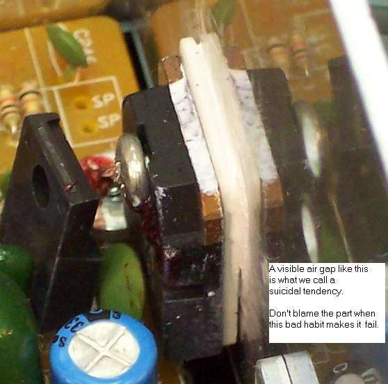
When those radios were being sold new we learned to unbolt these parts and add the missing compound. Even then we had plenty enough volume of repair work that we didn't need to send suicidal radios home with a customer.
Do you have a wattmeter?
A dummy load?
A multimeter to make DC-voltage measurements?
An oscilloscope is an unfair advantage, especially if you have learned how to use it.
It does permit you to do a sort of sideways "in-circuit" test of a final. A common failure is for the connection between the base and emitter legs to become an open circuit inside the transistor. A 'scope will show a much-higher RF voltage feeding into a blown final, since the input pin can't absorb the drive power when it's blown out.
But you need to know what the waveform looks like when the part is good for that reading to inform you about this.
Easiest quick test is to unsolder the base lead of each final and (GENTLY!) stand it up away from the foil pad on the pc board. Try not to bend the lead directly against the plastic body, or you may break it off from fatigue stress. Ground the negative lead of a typical digital multimeter. Ground it to the circuit-board foil ground, and *NOT* to the metal chassis. Select the "continuity" or "diode" test. Touch the now-isolated base lead with the red probe. Should read between 6/10 and 7/10 of a Volt. If it shows no change when you touch the probe to it, that one's dead, Jim.
73
How many bands are on yours? This will narrow down the age.
The oldest Saturn models will tend to have the longest laundry list of faults when they get past the 20-year mark.
Once it's old enough to buy a drink, we see a lot of them with toasted final transistors. The final transistors' metal tabs that bolt to the aluminum heat sink will be a dark, flat black color. This is the metal oxides that build up from excess heat. The habit back then was to "turn up" the bias adjustments, and cause excessive heat to cause the two finals and sometimes the driver transistor to fail.
The added current load to the final transistors has to pass through the modulator transistor. Some folks like to call it a "regulator", since it also controls the radio's carrier power in AM mode. This is what it looks like. Frequently the factory would leave off the white heat-conducting compound that fill heat-blocking gaps under the white insulating washer.
When those radios were being sold new we learned to unbolt these parts and add the missing compound. Even then we had plenty enough volume of repair work that we didn't need to send suicidal radios home with a customer.
Do you have a wattmeter?
A dummy load?
A multimeter to make DC-voltage measurements?
An oscilloscope is an unfair advantage, especially if you have learned how to use it.
It does permit you to do a sort of sideways "in-circuit" test of a final. A common failure is for the connection between the base and emitter legs to become an open circuit inside the transistor. A 'scope will show a much-higher RF voltage feeding into a blown final, since the input pin can't absorb the drive power when it's blown out.
But you need to know what the waveform looks like when the part is good for that reading to inform you about this.
Easiest quick test is to unsolder the base lead of each final and (GENTLY!) stand it up away from the foil pad on the pc board. Try not to bend the lead directly against the plastic body, or you may break it off from fatigue stress. Ground the negative lead of a typical digital multimeter. Ground it to the circuit-board foil ground, and *NOT* to the metal chassis. Select the "continuity" or "diode" test. Touch the now-isolated base lead with the red probe. Should read between 6/10 and 7/10 of a Volt. If it shows no change when you touch the probe to it, that one's dead, Jim.
73
Last edited:

Thanks nomadradio for info. I have transistor checker , multimeter, wattmeter and dummyload do not have oscilloscope. I could not find any voltages charts for this radio. I believe it has the 3600 board in it and thanks again.
if it has the 3600 board in it here is a trans voltage chart that will work. the trans numbers may be different , just look for the part number to verify you are testing the right part.
http://www.cbtricks.com/radios/galaxy/dx99v/dx99_trvolt_chart.htm
http://www.cbtricks.com/radios/galaxy/dx99v/dx99_trvolt_chart.htm
Okay, a 3600 board.
Doesn't answer the question about five or six bands.
But that's kinda typical. I ask questions that are obvious to anyone who cares to answer. The whole point is to gather information and narrow down where to look for the trouble.
Some folks choose to answer, if they're interested in helping themselves. Others not so much. It's all the same to me if you don't care about making it work.
The "3600" boards first appeared almost 35 years ago.
Not narrowing it down a lot with that. Not by itself.
The actual circuit-board type number could be a "EPT360010" if it's over 30 years old. A radio that old nearly always has more than "Just One" problem when we see them.
Could be a EPT360011 or EPT360012 if it's closer to 25 years.
They didn't make a lot of EPT360013 boards. The EPT360014 appeared in the early 90s.
That one came in a five versions, IIRC. A suffix letter follows the "14" to indicate which one you have. The production changed to the -15 boards around ten years ago.
So, it's a lot like "My truck is a Ford F-100"
Uh, what model year?
"Does that matter?"
73
Sorry for not replying nomadradio got busy with something else. My Saturn has bands A-F so a 6 band radio. I have not got back to radio been messing with a microphone that had been giving me problems. I really appreciate your replys and information and believe I am may have to take it to a tech and have him look at it. Will unsolder Base leg and check that before I do. I ordered finals and will be here any day. Thank You
dxChat
- No one is chatting at the moment.