• You can now help support WorldwideDX when you shop on Amazon at no additional cost to you! Simply follow this Shop on Amazon link first and a portion of any purchase is sent to WorldwideDX to help with site costs.

Galaxy saturn problem - meter readings

jrd426

Well-Known Member
Sep 5, 2018
195
120
53
56
Hi guys, I'm hoping someone can help me with a problem I have with a old galaxy saturn base. The signal meter when switched to sideband is way to sensitive and off the charts. If I reduce the rf gain it corrects the problem. AM signal meter reading with rf gain up is fine. Any thoughts on how to correct? Another meter I put in does same thing.
Many thanks!
 

Pretty sure VR1 sets the S-meter for AM and FM. VR2 sets it for SSB. Sounds as if someone has randomly cranked VR2.

Normally you feed a fixed level of receiver signal to the radio, like 50 uV and set the meter for S9.

If the trimpot has oxidized and gone bad, it may refuse to turn down.

73
 
  • Like
Reactions: Shadetree Mechanic
Thanks for the message Nomad. I tried to turn down vr2 with not much result. It knocked it back from vibrating off the scale to just solid off the scale. I wonder if the trim pot is shot. Other then this signal meter flying off the scale on ssb the radio seems to work great other then a high pitched noise coming from the frequency counter enclosure.
Wondering now if I should plan to replace vr2 trimmer
Many thanks
 
  • Like
Reactions: RT431
Wow!

When you have to trim VR2 AND RF gain, you may need a little more TLC around the AGC side of things for SSB modes.

IF you encounter problems with adjusting VR2 - then maybe you should look at IC1 and the AGC side of it.

Does your IC 1 look like this?
GalaxyAGCIC1.jpg

AGC in AM may work, but if SSB AGC is bad, you get symptoms like the above because it seem like it acts like too much or not enough - and everything sounds distorted.

So look over he parts boxed in Green, AM is red, so if you can see if you get power to SSB (Green) to help AGC action. So you see that AGC accepts power from the MODE selector...
GalaxyAGCIC1AMSSB.jpg

Hope this helps!
 
Last edited:
Thanks Andy for the message. My ic-1 is different.
 

Attachments

  • 15474841994056807473495144258207.jpg
    15474841994056807473495144258207.jpg
    2.4 MB · Views: 22
The schematic will apply - look at the R274 - 270 K same spot - so boards are nearly identical so all you need to do is locate the AM cap, then close by is the SSB cap C31 - Schematically it's a 47uF - but considering the age of that radio - it may have failed - it dried out - older electrolytic's turn into "dead shorts" when they do.

So it may bear to mention that you may have other quirks that will crop up on the older chassis like the Saturn - because of the quality of the Electrolytic Caps - their construction - will make them vulnerable to drying out.

So if you have a spare moment and a soldering iron and can work on it- may be worth to try and see if the cap C31 can be swapped out for another - or at least testing it with the DVM and see if R49 obtains a voltage from the SSB MODE feed - should show between 8V on resistor to about 3.3 V on the base of TR12.

TR 12 would have a signal on it from the AGC feed the VR1 and VR2 use from the AM and FM Detector as well as the SSB conversion of what's at TP6 C34 rectified and sent to IC1. So a direct DC check may not reveal anything - just easier to swap out the caps.

Caps themselves change the "Rate" of Attack and Decay of the AM and SSB signals that appear as a bias rectified from the detectors POWER it sees in the signals strength. It's processed and the out[put of Pin 14 of IC1 which basically tracks the PIN diode front end as attenuators. When SSB mode, the line affects where the attack and delay decay takes place on the feeder line to the IC1 input gate of that Quad Op amp Pin 12.

Heres' a little help to narrow it down...
GalaxyIC1C31C32.jpg

On your radio - there these two...
OnyourRadio.jpg

Hope this helps!

:+> Andy <+:
 
Wow Andy. You know these chassis's. Your tips are fantastic. I will try your suggestion and look at those caps and just replace them out. I cant thank you guys enough for your help and suggestions.
Best Jeff
 
The Galaxy chassis is the most studied and like the IBM PC - the open architecture platform for radio out there.

The more diverse, knowledgeable, other-wise just plain smart operators, whom are in radio - CB and Ham alike - use and abuse that chassis due to the Galaxy radios lines architecture being the way it is. They exploit the flaws, perks, Mods, Audio and AM regulation controls that allow for Direct Injection (Fidelity), Echo, Asymmetry mods - that can be developed - honed, sharpened and perfected - and as you can easily see - applied to nearly all the other radios of this genre.

They can easily lay claim to being what they are, and having their progeny scattered in DNA "Fingerprints" throughout the entire radio lineage even into Ham radio.

No matter what the demise of RCI or Galaxy as banes to the Radio Universe, they have brought many CB and Ham radio enthusiast alike, many hours of pleasure and fun - learning from this platform.
 
I guess they are what they are and agreed on the enjoyment many have had both using them and working with them. I will look for a good source to buy replacement caps of decent quality and take it from there I think. I have a few other similar that need to be all recapped as well. Many thanks for your time!
 
I know this is a old thread but I have a Saturn here that was no receive sound coming out of the speaker I have check everything it receive on the meter just know actual sound even check the specker jack and replace it what could it be ,
 
First thing to try is an external speaker. If it works, either the jack or the internal speaker has failed. The external-speaker socket has a switch contact inside that cuts out the speaker when the plug is inserted. This can shut down the internal speaker.

If you don't hear anything in the external, the next thing to try is to lay one finger along the shaft of a skinny screwdriver. Touch the tip of the screwdriver shaft to pin 4 of the TA7222 speaker amplifier chip. You should hear a loud hum.

If you don't either this chip has failed, or the connection downstream from there to the speaker has failed.

A voltmeter on pin 9 of the TA7222 speaker amp chip should read between 6 and 7 Volts DC, more or less. Pin 9 is the next-to-last pin at the rear-facing end of the chip. If it's a lot higher or a lot lower, either the chip has failed or one of the capacitors connected to it is bad.

Or both, maybe.

73
 
If the radio has not been re-capped in a while - or if you even know what Re-capping means - the AGE of the radio may be causing this...

But - I do digress, there are other things to check.

Since you say it receives, well, at least it does on the S/RF Meter - ok, half the battle.

Check CB/PA switch, SQUELCH controls

Any Hiss of noise from the speaker? You know, that "idle" noise floor - the radio "thunks" when you turn it on as the Audio path charges up and the speaker awaits for the bootstraps to finish collecting their charge - anything?

If its' "dead quiet" you may have a talkback wiring issue or D90 may have been messed with.

D90? Yes, that powers a line that "mutes" the Audio Amp Chip. There is also a Capacitor, not unlike the ones earlier in this thread - that can go bad and leave you stuck in "mute mode" until a voltage can appear and make C150 (the thump delay cap) work and hold a charge - if it's shorted (READ:Gone Bad) - it can leave that line low and never "boot up" because it is forcing/taking power out of the chip. D90 shoves power into it (TA7222AP) when in TX mode - to mute it. So if D90 is messed up or your CB/PA switches are corroded - well it can add to this problem.

Does TX and RX work? (1, 2, 3 - Red Light, Green Light - GO?)

You have a Squelch Amp too, that may engage but you'd at least hear a thunk because the Squelch amp just silences the audio line from the receive. Again it has a cap that can make your day...
AndycappRefill.gif

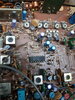
Now, you can look at Pin 8 of the IC 1 chip (The one in the middle centerline of the board) - note the photos used above, on that photo orient your board the same way - the Pin 8 is lower right-most pin of that BA 10324 - see if any voltages are on it. Switch PA / CB mode and check again. If it bounces or shows a change - that's not it.

If no changes then you may need to re-cap.
 

dxChat
Help Users
  • No one is chatting at the moment.
  • @ Wildcat27:
    Hello I have a old school 2950 receives great on all modes and transmits great on AM but no transmit on SSB. Does anyone have any idea?
  • @ ButtFuzz:
    Good evening from Sunny Salem! What’s shaking?
  • dxBot:
    63Sprint has left the room.
  • dxBot:
    kennyjames 0151 has left the room.