• You can now help support WorldwideDX when you shop on Amazon at no additional cost to you! Simply follow this Shop on Amazon link first and a portion of any purchase is sent to WorldwideDX to help with site costs.
  • A Winner has been selected for the 2025 Radioddity Cyber Monday giveaway! Click Here to see who won!

GME Electrophone TX560 Repair AM/SSB (PTBM146AOX), no AM RX, no TX

Ghetto

Active Member
Jun 22, 2010
80
46
28
Hey Guys,

I'm working on what I believe is a cybernet board: PTBM146AOX with a LC7131 PLL. This radio started my interest in trying to repair radios a year ago. Bought off ebay as untested of course :) Unfortunately I didn't have the soldering skills at the time and made a lot of beginner mistakes working on it fixing dry solder joints and replacing a few caps, wrecked a few tracks, bridged the odd thing etc.

At the time I didn't have the schematic either which really added to the confusion. It was a humbling experience and I put the radio away and spent a month training myself on circuit board soldering techniques etc and bought solder sucker etc. I've picked my game up and always understand the board electrically (whats connected to what) as as well as taking pics before working on it. Theirs no guessing (cringe....) anymore.

This board seems a bit rare , but not special, and no-one is talking about them on the net.

NOTE: Right now I'm focusing on getting the RX back 100% before worrying about the TX side (both driver and final tested fine out of circuit early on before I stuffed up the RX)

Original state: Received in AM and SSB with low volume but with warm up volume would reach normal levels and occasionally fading in/out once warm. Radio was on frequency. No TX output but switched between RX/TX fine.

Current state:
The radio had full volume on AM RX but very low volume on SSB. I believe this was due to my early stuffs up. ie I had lost ssb volume.

After re soldering some areas yesterday I've worked on using the schematic I lost AM all together (no volume, and now no RX light AM mode) but now have SSB receive at a higher volume but still not as loud as it should be, ie volume is at maximum for what I would call half volume. The SSB receieve is better (higher volume) after I found some dry solder joints under a metal plate solder side of board that I think was the back of the VCO block circuit but those dry solder joints werent part of the original work) as well as fixing a lifted track on Q16 (previous owner had glued track back on) Was listening to channel 35 DX skip yesterday while checking voltages - its on frequency.

btw, I believe the mode selector switch is working fine and that its something I've done.

I have a few questions:

- if the RX light is out on AM, does that mean the PLL is out of lock on AM?
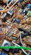
- Should I have R75, R78, R141 and J20 tied together?. What is J20? (see attached pic) I can't find R141 or J20 on the schematic thats at the end of the user manual I've attached. I had accidently bridged the earth of C106 thats nearby to the above resistor grouping. Maybe there was a knock on effect upstream/downstream and I damaged something?

I have few more questions/pics/areas of concern but I'm keen to work through the above first. Schematic is at end of user manaual attached. I wish it was of better quality but is the only version on the internet I can find.

Any help/direction is appreciated.

Regards,
Rob
 

Attachments

Last edited:

I managed to get SSB RX working much better and its close to being correct on volume level (still down a bit to what it should be but receive great). I found more dry solder joints throughout the board. I can't find any more.

I am still trying to get AM RX back. No RX light on AM, no volume, no RX.

Can someone tell me what transistor would be the electronic switch for AM? and what sections AM RX would be using that is separate to SSB RX. Schematic is attached. A lot of the schematic has similar layout to other cybernets.

The mode selector switch I believe is working fine. Its a not a TX/RX switching issue, the TX light comes on while on AM mode if microphone is keyed.

On AM RX, I have correct voltages on IC4 (AF AMP), IC5 (AF AMP), Q32 (AVR....What does AVR stand for?) and R132

Just looking for some direction as a beginner.
 

Attachments

(AVR....What does AVR stand for?)
The "VR" is for Voltage Regulator. Not so sure about the "A" part. Q32 steps down the main power down to 9 Volts, regulated to improve the stability of sensitive circuits.

The AM problem has to be a solder bridge. Only so many ways for a function to just "go away" all at once.

Any time this coincides with work being done like capacitor replacement, the odds favor an unintentional fault like a tiny bridge of solder.

73
 
  • Like
Reactions: Ghetto and Pez
Thanks Nomad, I might reverse all my solder work out briefly as I've already been over it many times comparing my work to the schematic.
 
Well a few months have passed and I have got nowhere on this (no AM RX). I've been trying, I don't think its a solder bridge as I've checked everything over and over many times with magnifier and continuity/resistance checks to make sure everything matches the schematic..

I gave it a lot of thought and believe I touched up a few solder joints while the radio was accidentally on and either shorted a component nearby or blown something from a transient earth differential from the soldering iron tip?

I had a lapse of focus (cow calling near me,on a farm this way) and forget to turn the radio off between testing/soldering.

** I need someone in teacher mode for 10 minutes to tell me the AM RX receive path to start tracing it. **

Example, I can see voltages on the [DC SWITCH] section changing based on what mode I'm in. For example on SSB RX I see voltage on Q28 and Q29 and when on AM RX I see voltages on Q30 and Q31.

In AM RX:
No volume\sound.
No RX led light,
[OSC 1] Q1 , [OSC 2] Q9 has correct voltages.
[IC 4] 4558 and [IC 5] AN7140 IC's has correct voltages.
[SWITCH] Q23 has correct voltages.
[AVR] Q32 has correct voltages.

I have no voltages on [IC3] SN76600 , [RF AMP] Q13,Q14, [MIXER] Q15, [IF AMP] Q16 and [AGC] Q21 but have correct voltages on those when in SSB RX.

Any ideas appreciated. I dont really care about this radio, but do care about trying to teach myself the problem solving skills/knowledge how to fix it.

Have been doing a lot of online reading/research on repairing radios trying to gain more knowledge/skills.
 
RX light is out on AM,
Has to be a power-supply rail issue downstream from the mode selector. No AM light sounds like no power to the AM receiver IF section, maybe.

Or maybe the AM bulb is just open. Unless the radio's last few users were sidebanders, the AM light tends to wear out first.

73
 
Last edited:
  • Like
Reactions: Ghetto
I agree its like the whole section is no getting power when on AM mode.

I just seen your edited response, I should of been more clear, this radio has a RX/TX led lights only. ie not band specific lights. The RX light (green led ) works on ssb for example. So i know the Rx light is good. TX light (red led) also works but am not working on the TX problem just yet. Wanted to get AM RX back and then switch to isolating the transmit problem later (no output but driver/final test good out of circuit)

I've only just found an online PDF editor where I can highlight, doing my head trying to memorize traces from the mode switch..

Could you tell me what diode is AM detect? not that I think its that simple..... I also assume the 455khz filter is for AM only?
 
@Ghetto

If you understood how a radio actually works, your explanation would have told you where the receive problem is, and I hope I'm right...................... but there could still be other problems with the radio.

When you say you have voltage at Q30 and Q31 means nothing, you have to check beyond them in the circuit.

The DC Switch circuits:
Q28 is SSB Receive.
Q29 is SSB Transmit.
Q30 is AM Receive.
Q31 is AM Transmit.
This means that receive gets turned off in transmit (when you key the mic).

You say that SSB Receive works, Q28 controls the SSB Receive voltage and it goes out through D34's banded end to turn on the receive circuit (also the light in the meter).

Q30 in AM mode feeds the AM Receive circuit out through D35's banded end. ........... Where the banded end of D35 meets up with the banded end of D34 to turn on the Receive and the light in the meter. (Note that in transmit D36 and D37 control transmit for AM or SSB with a voltage and also the TX light in the meter.)

Then while in AM Receive mode you should have a similar voltage as in SSB Receive mode where the banded ends of D34 and D35 meet. This is where you had questions about R75 which is part of the receive circuit.

If not either Q30 is bad or D35 is bad, because it is the only thing that controls AM RECEIVE and the light in the meter.

Follow the line on the schematic from the junction of D34 and D35 up to T2 and R58 and beyond .... all receive circuits that gets turned off in transmit.

Also note that Q30 also sends a voltage to D11, which may also need to be checked.

This is good example of how NPN and PNP transistors work in circuits, which makes it confusing to many people ... voltage turns on the NPN but turns off the PNP.

As you can see, checking for voltage at transistors also means checking beyond it to see that it keeps going in the circuit. Oscilloscopes are good for following signals through a circuit.

Also R141 could have been an add on to the radio after the schematic came out, it's up to you to find where it connects in the radio and add it to your schematic. ...... a very common practice back then and even now.

I hope you didn't mess with too many of the tuning slugs, you'll have hell to pay for that without a service manual.

Good luck

73
 
  • Like
Reactions: Ghetto and Tech5
Thankyou so much for your reply, that's the detail I am after.

>If you understood how a radio actually works

Exactly! Thats my problem for sure! :) I don't understand the fundamentals which is why I've been teaching myself online the basics to how the circuit works.
I need to conceptually get my head around the basic radio design/circuits/electronic component principles in order to have the problem solving skills. I've been doing a tonne of reading trying to get up to speed. My background is a computer programmer. This is a hobby for me.

I will start working through your detailed reply, I'll test Q30 and D35 and work my way through the traces with your detail and see what I can find. I really appreciate the time you've spent on this.

>Also R141 could have been an add on to the radio after the schematic came out

I'm pretty sure I have that junction right as SSB RX is working good. But it messes with my beginner head when they do that! (or get screen printing wrong for capacitor polarity vs schematic)

>I hope you didn't mess with too many of the tuning slugs, you'll have hell to pay for that without a service manual.

No I haven't messed with any tuning slugs. I leave them alone until I have the proper test equipment and procedure for alignment. I understand messing with tuning slugs could make the radio entirely inoperable.

I'm keeping an eye out for a frequency counter and and oscilloscope online. The only oscilloscope I have right now is a vintage 10mhz unit which I don't think is much use.

Rob
 
@Dr. Frankenstein

Finally got a chance to start looking at it today.

Your spot on! D35 is the culprit, lifted a leg and its open. Can see the voltage stop there as well that I expect to see up in the receive chain trace R75 is connected to.

Thanks for wasting your time on me.

D35 is a MA150 diode, can i substitute with a 1n4148? or should I pay the extra $$ for MA150s I can see available online?

Will keep working through everything you've said as well as rechecking R141 etc, just wanted to give you a quick update. Thanks again for the detailed description of the circuit for me.
 
Just a quick update: Transmit is 100% working!!!! After months going around in circles spending an hour here and there tracing voltages and testing components that all checked out good I worked out Q22 [SWITCH] base was not getting its 0.7v on TX and I kept loosing the voltage for it on the board so I changed tact to look more at the via holes and found a single via hole problem - touched up via with solder and its 100% reliable on TX.

TX is appears to be on frequency with proper output watts etc. I am so happy!! I do want to check bias ma for driver and final (I heard cybernets can sound cr*p on ssb due to low biasing) but it appears I may need to lift legs/desolder based on youtube videos I've seen. Wish they were like my PC385 board on trc490 where you unplug each wire to put in series with ma meter...

My only remaining problem is low volume on SSB RX. I've improved it after finding C102 had a dry solder joint to ground (C102 connected to pin 4 and 6 of IC3 [IF AMP] SN76600) I've also recapped (just electrolytics) a fair bit of this radio as well hoping it may be a cap problem. You have to put volume at full to have at a level you would normally listen to comfortably that would be at half way for example.

AM receive has good volume, ~ twice the volume on SSB

As a beginner I always have questions if anyone is keen to look at the schematic for me... (pretty please!!):

1) I'm focussing on what I think is the SSB receive section but need confirmation I'm looking in the right area. btw SSB is receiving well (sensitive) and on frequency:

IC3 [IF AMP] SN76600)
Q16 [IF AMP]
Q17 [SSB DET]
Assuming AGC section is also used?, I did recap C134 and been looking at that area as well but does AM use AGC? If so then its probably ok?

Voltages generally ok on transistors, IC3, other than I note I have 13.7v on one end of R80 (100ohm, tested ok) that supplies T11 that supplies Q16 collector supposedly 12v but I get 11.7v. I dont know if that would reduce volume (0.3v difference) and if something is dragging it down connected to T11?

I'll keep trying with my limited knowledge but if anyone has any ideas or hints to fault finding this low rx ssb volume then I'm all ears!!!!
 
Last edited:

dxChat
Help Users
  • No one is chatting at the moment.