If it were an a 18 foot long half wave it could achieve a power gain of zero. As a loaded 1/4 wave it's power gain is a negative number.It isn't 56 inches long electrically though as it has a capacity hat which will make it appear electrically longer than its physical length.

You are using an out of date browser. It may not display this or other websites correctly.
You should upgrade or use an alternative browser.
You should upgrade or use an alternative browser.
-
You can now help support WorldwideDX when you shop on Amazon at no additional cost to you! Simply follow this Shop on Amazon link first and a portion of any purchase is sent to WorldwideDX to help with site costs.
-
A Winner has been chosen for the 2026 July 4th Retevis RA89R Giveaway! Click Here to see who won!
GOLDENROD 45
- Thread starter Mudfoot
- Start date

Never have used one of those hear some good things about them.. I would love to find the build plans for Signal Engineering old base antenna Goldenrod 180S Had 3 of them until Jan 3 2000 granted they were only 1/2 wave But at 50 feet to the feed point I could hear stations the most of the others couldn't hear
455, I can't find any reference to a Goldenrod 180S. Since you had 3 of them, do you have a manual, an advertising flyer, or an Internet link that describes this antenna.
I recall HyGain making a Silver Rod and a Golden Rod antenna and I think they were both were 1/2 wave ground plans and they had 3 short curved ground radials.
Signal Engineering made an earlier mobile model called the GR-45 Spyder A Plus. Later they made the revised version that is 56" long overall.
Last edited:
I did some non scientific test with it. I worked better then a Wilson 5000 and equal to a 102" wip.
Then it turned into a pretzel.
Then it turned into a pretzel.

Thanks Dr_DX.
I found this image of the Goldenrod 180S below. I remembered the antenna after seeing your post.
455, I'm not surprised you had good results with this antenna. For years I mostly used a Starduster that always worked great for me. It looks to be very similar to the SD'r design.
I found this image of the Goldenrod 180S below. I remembered the antenna after seeing your post.
455, I'm not surprised you had good results with this antenna. For years I mostly used a Starduster that always worked great for me. It looks to be very similar to the SD'r design.
Attachments
If it were an a 18 foot long half wave it could achieve a power gain of zero. As a loaded 1/4 wave it's power gain is a negative number.
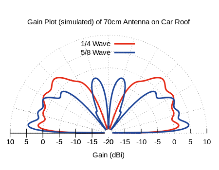
Depends on what you're measuring. If its dBi then it could be >0, if it is dBd then it is highly unlikely but it is perfectly possible to have dBd gain which isn't a negative with a quarter wave depending on the quality of the ground. A car roof for example is effectively a perfect ground for a 1/4 wave antenna on 70cm and you end up with a plot like this which will give you gain of up to 2-3dBi and 0dBd:
I had forgot that it looked like a "Starduster" been so long that I had one last one I had was tore up when my storage building was destroyed Jan. 3 2000 when a F3 tornado hit my area.Thanks Dr_DX.
I found this image of the Goldenrod 180S below. I remembered the antenna after seeing your post.
455, I'm not surprised you had good results with this antenna. For years I mostly used a Starduster that always worked great for me. It looks to be very similar to the SD'r design.
I could hear them I could talk to them
455, I'm having difficulty modeling the SE 180S. Could you tell me what the radial bracket is made of, the part in the image above that supports the bottom of the radials?
I should also add, based on your answer to the question above, this antenna could be more similar to an AstroPlane instead.
I should also add, based on your answer to the question above, this antenna could be more similar to an AstroPlane instead.
Last edited:
The advertised claim was "power gain", not db gain. I've never worked with any isotropic reference for power gain although, it may exist. Power gain typically relates to the ERP when compared to 0dbd. In any event, I think we can agree this is mostly marketing hype. I can say, these antennas have been shown to work good skywave along with some other top loaded models. Not sure what the reason is or if it's better than an unloaded 1/4 wave because comparing antennas in DX is a relative comparison at best.Depends on what you're measuring. If its dBi then it could be >0, if it is dBd then it is highly unlikely but it is perfectly possible to have dBd gain which isn't a negative with a quarter wave depending on the quality of the ground. A car roof for example is effectively a perfect ground for a 1/4 wave antenna on 70cm and you end up with a plot like this which will give you gain of up to 2-3dBi and 0dBd:
It had a wire about 14ga dont remember the length of it the wire went through a plexiglass bottom that was stretched not tight but taunt had 2 holes that the wire passed through the ends of the wire attached to a aluminum bracket made a triangle shape from the top bracket the radiating element was isolated and attached to the aluminum top bracket coming out of the SO-239 was a 14 ga wire that attached to the radiating element......Measurements I cant remember....I have also been told that it could be a "Vertical Dipole" of sorts It only weighed 2.5 pounds simple to assemble. All of this is from memory and some noted I kept wish I had kept more information on it.455, I'm having difficulty modeling the SE 180S. Could you tell me what the radial bracket is made of, the part in the image above that supports the bottom of the radials?
I should also add, based on your answer to the question above, this antenna could be more similar to an AstroPlane instead.
Thanks for you reply.
Here is another image that looks closer to what I remembered, with a plastic radial support bracket at the bottom.
Did the wire end on each side of the bracket at the holes, or did the wire run across the bracket and back up the other side to the upper bracket, making the wire a continuous length for the rectangle you mention?
Attachments
Last edited:
Yes the one I had the bottom was a clear plexiglass about 3 inches wide cant remember how long but thats itThanks for you reply.
Here is another image that looks closer to what I remembered, with a plastic radial bracket at the bottom.
It had a wire about 14ga dont remember the length of it the wire went through a plexiglass bottom that was stretched not tight but taunt had 2 holes that the wire passed through the ends of the wire attached to a aluminum bracket made a triangle shape from the top bracket the radiating element was isolated and attached to the aluminum top bracket coming out of the SO-239 was a 14 ga wire that attached to the radiating element......Measurements I cant remember....I have also been told that it could be a "Vertical Dipole" of sorts It only weighed 2.5 pounds simple to assemble. All of this is from memory and some noted I kept wish I had kept more information on it.
455. if you check the PDF image details below, I think you'll see the dimensions you need. The image itself is a bit misleading. IMO, the image on post #26 above looks more like the antenna that we both seem to remember as a better indication of its construction.
I have the model of the Goldenrod 180S in Free Space working now. I think it is the way it was designed to be constructed. I want to do it over real Earth and make an overlay to see how it compares to the a few other vertical 1/2 wave antennas first. If I don't run into some snag in this process...I'll post the model later.
Attachments
I have one on my 2022 Frontier. nothing but good reports and not directional like 102" whip I had been running. Less noise also I can talk in places I couldn't before due to noise SWR 1.18 on 21 about the same across the band. I use a AT-500M in truck and it drives my KL-503 from 40 dead key to around 250 Watts while talking my CB friends say they hear me much better now.directional on a mobile may be alright if stationary. Not really sure how directional it is or the flat side claims. Would like to know more about this antenna as I've been looking at them as of late.
Lightning Antenna dot com
and YouTube
and they are on ebay.
dxChat
- No one is chatting at the moment.