since you dont understand the question,
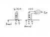
i attached a picture of what it looks like you have done, can you tell me if this is correct ?
I'll let someone else show you how to attach pictures to posts.


since you dont understand the question,
i attached a picture of what it looks like you have done, can you tell me if this is correct ?
should i use CHICKEN WIRE if the leads from the resistor are too short ? lol
mackmobile43 said:Remove the 270k from the board totally, connect one end of the 100k in it's place, solder the other end of the 100k to one of the outer legs of the 2 meg pot, solder the other outer leg of the 2 meg pot back to the other hole where you removed the 270k resistor.
It is a simple series loop of a resistor and a pot.
Adjust the 2 meg pot until the desired tone is achieved.
Remove the 270k from the board totally, connect one end of the 100k in it's place, solder the other end of the 100k to one of the outer legs of the 2 meg pot, solder the other outer leg of the 2 meg pot back to the other hole where you removed the 270k resistor.
It is a simple series loop of a resistor and a pot.
Adjust the 2 meg pot until the desired tone is achieved.
first of all, your the dumb shit and totally have no understanding of anything electronic what so ever and should never post anything on the internet as it has taken me now 10 post and you still havent explained WHICH lead from the resistor.
dont worry about it.
i;ll ask someone with an IQ to help me as you dont know anything about anything.
do you realize that if you place the resistor in the wrong way, you will be putting the POT before the circuit and there for, it will not work correctly.
go back to school and stop hanging around RADIO SHACK maybe you'll learn more words other then SERIES and PARALEL.
i still think you bought the mic that way and whom ever sold you that mic dropped a few techinecal words for you to use .
i;ll figure it out myself, i just didnt want to have to solder it in 2 times and hope one of them worked.
PLESE DONT REPLY AND WASTE ANY MORE OF MY VALUABLE TIME.
GO EAT A PIZZA
All you are doing is replacing a fixed value resistor with a fixed and a variable resistor in series.do you realize that if you place the resistor in the wrong way, you will be putting the POT before the circuit and there for, it will not work correctly.
All you are doing is replacing a fixed value resistor with a fixed and a variable resistor in series.

How are you going to have adjustment? Aren't the 2 outer legs fixed?remove the 270k resistor, solder one end of a 100k resistor in one hole where you removed the 270k resistor, at the opposite end of the 100k resistor you just installed in place of the 270k resistor solder one lead of the 2 meg pot, clip the center leg of the 2 meg pot because it is not needed, solder a length of wire to the other outer lead of the 2 meg pot, solder that length of wire back in the other fucking empty hole left by the removal of the 270k resistor.
first of all, your the dumb shit and totally have no understanding of anything electronic what so ever and should never post anything on the internet as it has taken me now 10 post and you still havent explained WHICH lead from the resistor.
dont worry about it.
i;ll ask someone with an IQ to help me as you dont know anything about anything.
do you realize that if you place the resistor in the wrong way, you will be putting the POT before the circuit and there for, it will not work correctly.
go back to school and stop hanging around RADIO SHACK maybe you'll learn more words other then SERIES and PARALEL.
i still think you bought the mic that way and whom ever sold you that mic dropped a few techinecal words for you to use .
i;ll figure it out myself, i just didnt want to have to solder it in 2 times and hope one of them worked.
PLESE DONT REPLY AND WASTE ANY MORE OF MY VALUABLE TIME.
GO EAT A PIZZA
CANOLLI said:which side of the resistor is removed from the board ? ,it looks like the top lead was removed and soldered to the pot after replacing the 270 k resistor with a 100 k resistor then the lead from the other terminal from the pot goes back where that top lead came from back into the board.
am i correct ?
the picture is very difficult to see exactly how you did the mod.
thanks again
Dave from toronto