• You can now help support WorldwideDX when you shop on Amazon at no additional cost to you! Simply follow this Shop on Amazon link first and a portion of any purchase is sent to WorldwideDX to help with site costs.
  • Click here to find out how to win free radios from Retevis!

Grid-driven Tetrode Input Circuits

Saturday: The Inductance to ground running parallel to the RF input from the 50:450 unun is what was missing. I do not understand why 750 ohms swamping resistance is the optimum value given the 50:450 ohm unun, but 750 is spot on. I used a 10T Pot in place of 750 ohm fixed and 750 shows a pronounced dip on the swr analyzer.

Deciding whether to follow Inductance values or the # of Toroid Turns for each band (10-11-20-40) was my primary issue. I went with uF values/readings but now it's clear I should follow the number of Turns instead as each of my 4 uH starting values were too low. Just a bit of rewinding and I should be set to re-assemble.
few more days until I can drive it but soon. Waiting for resistor delivery before I can try it.
neil, NYC
 
Last edited:
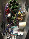
Seems that way yes. I thought I had it working several times when attached to a DL. That was far short from an antenna. The impedance formula remains over my head with the imaginary value. I'll stick to copying circuits where I have a chance at success. Should receive the resistors by weeks end, then try it again. Thanks again Nomad for measuring and publishing the details on the DX-300. Pic is minus the 750 ohm resistor to RF ground. RF Input.JPG
 
  • Like
Reactions: AudioShockwav
Pride RF Input Circuit Copy

Initial results from my copy of the Pride RF input circuit are encouraging to the extent that I see improvement on 10-11-15. 20M continues to be a dead zone. I note the Pride plate choke was 55uH while the Ameritron-ish AL-572 choke I’m using is about 200uH. (RF Parts purchase pre-2010).

Amp is still on work table so all results are into a DL and powered by low current AC outlet. Plate current is limited to the single chassis-mounted transformer (1.8kv @ 400mA).

The RF input I had previously was a 1:6 unun, RF grounded with a 300 ohm swamping resistance to RF ground. It provided only 1 value of inductance (the unun coil to RF ground itself) for every band. The Pride input circuit allows me to select a different inductance to RF ground for each band. A 4PSP switch allows for a different inductance to RF ground for each band (10-11-20-40). I also added a series connected, slug tuned inductor (1.5 to 1.8uF) I can switch in and out via a toggle to add some to each position for comparison.

I’m still unfamiliar with the new and higher drive level imposed by Pride 750 ohm swamping resistance. I expected drive requirements to decrease from the higher 750 swamping resistance. While the Pride values were for 1 tube and I have 2 tubes, 750 is still more than double 300 ohms.

In any event, I’m working on the presumption I can double the Pride drive limits because I run 2 tubes instead of 1. (10w AM / 25w PEP)
Gotta run later,
neil, NYC
 
If this were a cathode-driven amplifier, the drive for two tubes wouldn't quite be double. Putting two tubes in parallel doubles the transconductance. Twice the anode current for the same grid voltage. More power from the exact same drive voltage.

Since the RF drive power is pushing current into the cathode circuit, you'll need a little more drive for two tubes than for one, but not nearly double.

Grid drive is almost entirely about voltage. Only tiny bit of the RF drive current reaches the tubes, 10 percent or less. As such, the exact same RF drive voltage will drive two tubes the same as it drives one. But this is only strictly true for class AB1, where the drive level is held below the threshold where the grid draws current.

Class AB2 is more the rule, especially for AM. I would predict that two tubes require about ten percent more drive than one tube using grid drive.

Mind you this is an educated guess, in light of the fact that the tubes absorb at most ten percent of the RF drive power. The other ninety percent warms up the swamping resistors.

Of course, the unwanted positive feedback in the grid circuit also contributes to warming the swamping resistors. Not a lot, but that's what they do, is absorb that regenerative feedback so it can't make the tube oscillate.

73
 
I'm stumped with the higher bands. 40M PO is at times, stunning (factor of 100x no problem) and easy to tune. 10-20 no more than 60w from the same 5w drive and it's really hard to tune. Swapped-out plate choke from approx. 200 to 125uH (Heathkit-sized porcelain form approx 1/2" diameter, 28 gauge). 40M worked even better but more of the same from to 10-20. Ideas, suggestions?

EDIT: Poking around testing this and that I learn that my swamping resistance is very inductive at 98H. Thought it was NI being MOX. Apparently, I'm mistaken big time. Far higher than all my other known NI resistors. Search, order, wait for delivery and see, repeat. Maybe this is it, I hope so.
 
Last edited:

dxChat
Help Users
  • No one is chatting at the moment.
  • @ BJ radionut:
    those boys in Louisiana going to be hard to live with...working those HI stations...my buddy Greg KK5SW/4 elements @35ft/350 watts...2 HI contacts today!!!! Arnold KE5JXC snagged one also!!!
    +1
  • @ Mark Malcomb:
    Hello BJ. Been a long time since I've been on. You doing well? Mark Malcomb
  • @ Naysayer:
    I’m