• You can now help support WorldwideDX when you shop on Amazon at no additional cost to you! Simply follow this Shop on Amazon link first and a portion of any purchase is sent to WorldwideDX to help with site costs.

Grid-Driven Tetrode Input plan #2

Naysayer

Solder Balls
I Support WorldwideDX.com!
Mar 6, 2020
286
217
53
New York
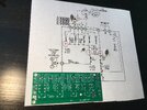
I scrapped the messy rotary switch inside blower box in favor of a relay switched, parallel inductance to RF ground for driving the grid-driven tetrodes. I re-purposed a four (4) band LPF board to reduce lead length and add a nice ground plane for the connections & components.

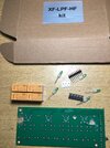
The LPF board is available as both a kit form and fully assembled. I got the kit so I could modify the board and replace the supplied inductors with the ones I already verified as working. I’m omitting 80m which is an easy add-on if wanted later.

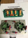
The pcb is 2-sided with the bottom being a large ground trace except for the thru-hole component points. I used a Dremel to remove trace material where needed. Lots of room as half the original inductors are omitted. Each band will have it’s own .01uF cap to ground so I can use small components.

Board will need only 4 connections: Ground, RF In, bias V In and bias V Out. A simple wire will parallel the relays to joins with the bias V at tube grids. Small enough to fit inside tube deck. Every connection except ground will be screw-tightened posts soldered with a spot of epoxy for strain relief. Ground will be solid wire soldered both ends.

My entry-level soldering station finally died. Yet, that’s good thing as needed a better one. Not a big jump-up but a step in the right direction. Hopefully delivery will be soon.
 

Attachments

  • Tuned Input plan 2.JPG
    Tuned Input plan 2.JPG
    1.6 MB · Views: 36
  • Tuned Input plan 2a.JPG
    Tuned Input plan 2a.JPG
    1.7 MB · Views: 32

Lost my SMT virginity today.

She was a 6k8 resistor and small, hard to see even. Part came with the LPF kit I will try using for input board. Also solder station upgrade delivered; Ceramic tweezer set & watched some YT vid on SMT work. Have 4 SMT diodes for the relay coils but they larger and I can see the line on 1 side so I can figure that out. 6k8 was easier than I expected and 1st time using the new solder setup which taught me I should have gotten a better soldering station long ago.

I’m looking forward to trying the new input board on the Tetrode amp. It cleaned up my input wiring. I configured board so I can swap out the resistive load to RF ground without major surgery. I going to lower the 750 ohm resistive load to 600. Pics soon.
neil, nyc
 
  • Like
Reactions: AudioShockwav
Rebuilding RF deck to install relay controlled RF input board for 10, 11, 20 and 40. I’m replacing everything beneath sockets. The 10 pos rotary switch (mess) helped narrow the inductance needed for two 4cx300a tubes. I’m sure there were easier ways to do it but the formulas were over my head & I did not have the proper meters but then again even if I had the meters, it would become do I have the ability/time to learn how to use them. Can’t just pick up a VNA and use it like a VOM, I know that much. The journey is half the fun but Senior Citizens gotta be realistic when it comes to time management.

The cores that came with the LPF kit were discarded and the ones in the picture are ferrite. The 20M core (larger red w/ orange Tefl covered wire) has 11T solid 20awg, w/ no ceramic cap. I wound the Red on a lark being frustrated at not getting the smaller yellow cores/magnet wire & ceramic cap combos to work. Second best was smaller yellow with 13T magnet wire but it was far worse.

The orange on red (20M) requires noticeably more watts to get similar PO but worked better than the smaller Yellow cored Turn combos I tried. The 10M has 2T, 11M 3T and the 40 same T as specified in the Pride DX200 treatise by w8ji except the ceramic is 8pF not 39. The foregoing is what worked best when I had the rotary switch test-setup. I tried many combos over a week or two. It was all that core testing that popped something so I have some control board trouble shooting after the deck is together. Believe it or not, the Tet Boards are easier due to the instructions. I can just replace parts until it they work again and socketed IC’s are a snap to test.

There’s so much more room in the air box with the wires and rotary switch gone. I hope the relay board doesn’t mess up the match much but if it does, it’s easier to remove & adjust. Board has 3 screw-tightened posts for external connections (RF IN, Bias vdc, Tube drive) except Ground which are ring terminal leads. Anchored with epoxy both sides.

The large resistors are 14w 350R NI type. 700 should be close enough but only time will tell. I’ll eventually try 600R. The JXT connecters keep it all inside the box with 4 LED indicator for each band. New feed-thru caps for certain wires. Once I saw what 2 of these tubes could do, I wasn’t giving up.
neil, nyc
 

Attachments

  • RF Input Board near complete.jpg
    RF Input Board near complete.jpg
    118.6 KB · Views: 22
I got it all inside with room to spare. Won’t miss that rotary band switch at all. Relay band switching sounds like a luxury to me. It will be a long time before I try it as I disassembled soft-start and other sections in a general housekeeping effort. Got a new set of IC’s just in case that Bang event was Tetrode board related
2EEA45FC-1824-4F7E-8C5F-9FF321B8B741.jpeg
 
  • Like
Reactions: AudioShockwav


Write your reply...
dxChat
Help Users
  • No one is chatting at the moment.


      You do not have the permission to use the chat.