• You can now help support WorldwideDX when you shop on Amazon at no additional cost to you! Simply follow this Shop on Amazon link first and a portion of any purchase is sent to WorldwideDX to help with site costs.

Homebrew antenna switch box

caspear1978

Member
Jan 8, 2009
84
1
16
45
I've been trying my hand at building an antenna switch box. So far its working.

But when i have it inline my swr goes up to 1.7 -2.0..

With out it inline the needle barely moves across the 40 channels.

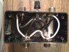
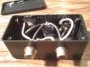
How I've got it constructed is by using a 2x3 plastic project box.

I've used spare parts from old radios for the coax connectors.

And I used a 3 position mode switch from a cobra 142 that i had for parts as well.

The wires used inside are from a piece of coax that i had a length of laying around.

The grounds i have connected to each coax connector but not to the switch and is just a piece of wire i had laying around but not coax.

What I'm trying to figure out is why my swr goes up with it inline.

Could it be the switch or the ground wire that is causing the swr to go up?
 

The problem is really the way it is constructed. First it should be a metal box. That shields everything and makes a complete RF tight enclosure. Secondly, the wiring adds stray capacitance and that will detune your system. With a metal box all you have to do is wire the centre pins to the switch and not worry about the grounds as the box takes care of that. Also switches should be of high quality with rotary ceramic types being preferred. Simple toggle switches will work but are far from the preferred type. Wiring RF circuits is more critical than a simple audio or power supply circuit.
 
Robb, Here are 2 pictures of the box for you.

BOOTY, From reading Captains post I am starting to see that now.

Captain, Thank you for the info, You have helped me see where i went wrong in my set up and will try again as you have suggested.

I will post again after i have made another box and used a different switch.

Thank you gentle men for helping a beginner on the learnings of Home brewing.

Mark
 

Attachments

  • Picture 007.jpg
    Picture 007.jpg
    54.6 KB · Views: 1,984
  • Picture 008.jpg
    Picture 008.jpg
    56 KB · Views: 2,047
i was just guessing .
hey cap'n kilo , if he wrapped it in aluminum foil making contact with the 239s ground side would that work enough to show if a metal box will fix or help ?
 
i was just guessing .
hey cap'n kilo , if he wrapped it in aluminum foil making contact with the 239s ground side would that work enough to show if a metal box will fix or help ?

It may but from the pix I would say the switch is a big part of what's wrong. It's just not meant for RF. It may work for a barefoot rig but I would not run ANY type of power thru it. Also try and keep the wires as short as possible, that is a big factor.
 
Could he use short pieces of RG-58 coax to wire it inside and keep the shields grounded at a common point?

Good idea Robb. I am sitting here half asleep and never thought about that. I did the same thing when upgrading my MFJ 1700 switch. It would only work on HF and I needed it to work on 6m as well so I cut out all the long buss wires and replaced them with short pieces of RG-8X coax cable. That dropped the SWR on 6m from over a 3:1 down to about 1.15:1. I left the coax braid connected to a common point ground on one end only. The end that went to the switch was simply left open and as close to the end as possible without shorting.
 
After looking at the pictures again, I can see that he has coax in there already.
But I can't tell if he used the braid on the coax as a common ground - and if all of the connections are made with coax.
Maybe that is what he might try next - also use the outside metal of the switch for grounding . . .
 
As the picture shows there is no connection of the coaxes shielding to a ground source and the coaxes are in fact radiating as an antenna should.
 
As the picture shows there is no connection of the coaxes shielding to a ground source and the coaxes are in fact radiating as an antenna should.


You are right. Without the shields grounded they are simply unshielded wires. Connecting those shields together and connecting them to the coax connectors will help somewhat.
 
I decided it was time for me to look back at what every one has wrote and seen where i went wrong.

1. I went with a plastic box. hooked up grounds. Still no luck getting swr down.

2. Switched out the switch for one stated before. Still no luck.

3. Went out and bought an electrical outlet box. Drilled the holes where i wanted them and wired everything up. And low and behold my swr went down to where they are suppose to be.

4. Tried both switches and neither showed any difference in swr. i don't plan on running power at this time through this switch except for whats coming out of the back of the radio.

Everything is working fine now on the inside of my shack so now its time to work out side.

I have my PDL-2 that is getting moved to the chimney and mounted on a rotor.

I have an Astro-plane that will be going where the PDL-2 is mounted now.

I will measure when i get up there what the distance is between the 2 antennas and space them out more if needed.

Thank You everyone for your tips and pointers,, Mark
 
This is a neat build. I think I may use a similar layout to build a station switch (for changing radios instead of antenna) since I have one antenna and a couple radios and want to switch between them without unhooking every time.

question how much would it hurt to use a slightly bigger box for ease of working in my fingers are kind of gaumy, would a little longer wires hurt the design? like using a 2 gang box instead of the single shown?
 

dxChat
Help Users
  • No one is chatting at the moment.
  • @ Wildcat27:
    Hello I have a old school 2950 receives great on all modes and transmits great on AM but no transmit on SSB. Does anyone have any idea?
  • @ ButtFuzz:
    Good evening from Sunny Salem! What’s shaking?
  • dxBot:
    63Sprint has left the room.