• You can now help support WorldwideDX when you shop on Amazon at no additional cost to you! Simply follow this Shop on Amazon link first and a portion of any purchase is sent to WorldwideDX to help with site costs.

Homemade Antenna and Radio theory.

LumpySnake

Member
Mar 3, 2009
11
0
11
35
The other day I decided to make my own base station antenna. So I did.
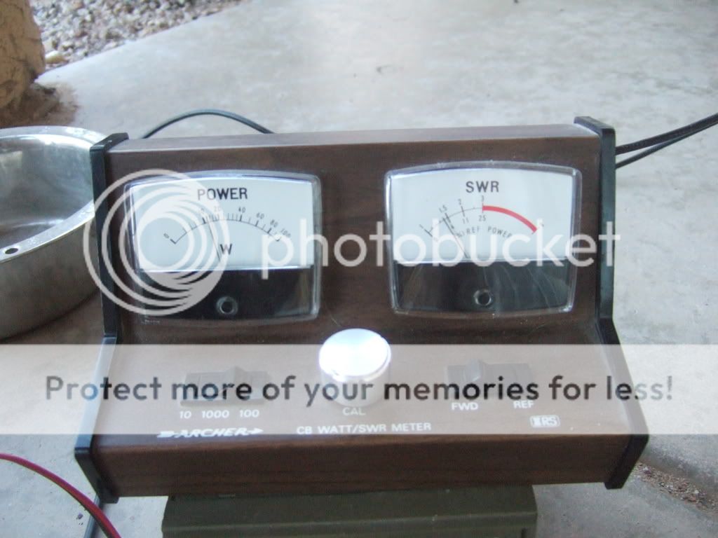
And it works, quite well actually. I got my SWR down to 1.1
on the channel I want. However my meter shows im only getting 2 watts of power.

After fiddling around with it for a bit i found i could get the full 4 watts of power. But my SWR is in the range of 2 and 3. My question is, why would an antenna produce more power improperly tuned than a properly tuned antenna?


For those of you wonder here is my setup. Brace yourselves, its not pretty.
There are a couple of old pictures from previous setups in there but its still pretty much the same.

Oh and sorry for the giant pictures I don't know how to make it not do that.

The antenna is based around a piece of PVC pipe stuck in a cinder block

DSCF0006.jpg


DSCF00102.jpg


I ran my COAX to the base of the pipe. I split the wire to reveal the copper core and outer braid. I then attached via alligator clips, the Driven element to the core and the 4 ground plane wires to the copper braid.

DSCF0004.jpg


The 4 ground plane wires are held in place by a state of the art red brick anchoring system. :p

DSCF0001.jpg


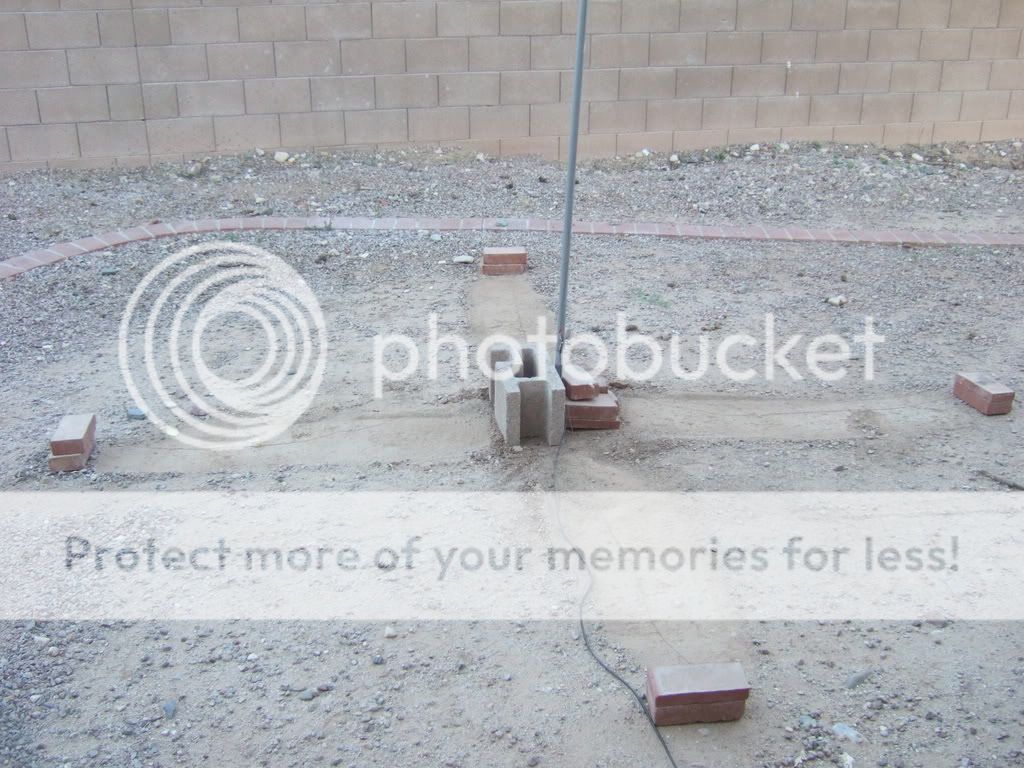
The driven element is held to the pvc pipe with tape. Not even good tape either just this stuff.

Scotch-Tape-Roll.jpg


DSCF0005.jpg


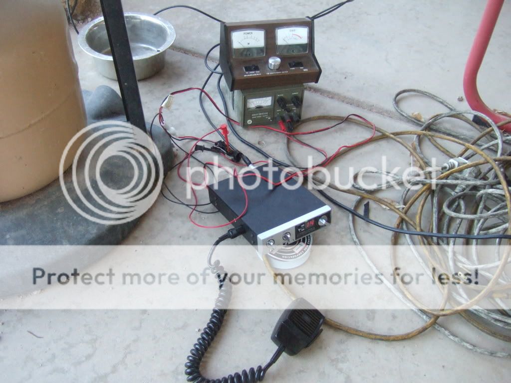
my radio setup is a real sight too. Its not even a base radio. Its a mobile with the cigarette lighter plug split open and 2 clips running from it to a power supply which just barely supplies the proper amperage.

DSCF0007.jpg


1.4 SWR and 1 watt?

DSCF0008.jpg
 

My question is, why would an antenna produce more power improperly tuned than a properly tuned antenna?/quote]

well, i just don't know where to start.;)

congrats on the "design"

the antenna doesn't "produce" any power, the transmitter produces the power. the xmitter wants to see 50 ohms, thats where it is happy and it should produce max output into a 50 ohm load. so if your adjustment shows more power (then no matter what your swr meter shows) you are getting closer to 50 ohms.

can you raise the entire thing? your radials are in contact with the earth and are being detuned.

also, try to solder the connections, the tape/alligator clips really doesn't get it :love:
upgrade the power supply and hard wire the connections.

i'll stop here and let someone else comment
 
If your watt meter shows more power out, the radio is 'happier'. Tune for maximum 'smoke' :) The SWR meter may be a bit out of whack, because in general, less reflected means a better match and the radio will be putting out higher power as a result. Generally they go hand in hand so something is askew with that meter maybe.
 
Your power meter is probably reading superposition of both the forward and reflected wave. It's a votlage device, right?

I get the most power when I run into a direct short? Or was that an open?
 
If your watt meter shows more power out, the radio is 'happier'. Tune for maximum 'smoke' :) The SWR meter may be a bit out of whack, because in general, less reflected means a better match and the radio will be putting out higher power as a result. Generally they go hand in hand so something is askew with that meter maybe.


So I should just tune it until it puts out the most power?

Also I am wanting to experiment with co-phasing antennas.

I have been reading up on it and some of the articles I have read say I need 75ohm coax. Would it reduce performance if I used standard 50ohm?
 
how long is the radiator? the radials? did you compute the dimensions or just use a random length?

also try a "choke" @ the feedpoint(5-6 loops of coax about 6 inches in diameter)
you have an rf ground, how about an eletrical ground?

here is a link i posted in another thread... http://www.hamuniverse.com/basicantennas.pdf its good info to have handy.
BTW.... are you in so Cal? that DG (decomposed granite) dirt looks familiar
 
Last edited:
how long is the radiator? the radials? did you compute the dimensions or just use a random length?

also try a "choke" @ the feedpoint(5-6 loops of coax about 6 inches in diameter)
you have an rf ground, how about an eletrical ground?

here is a link i posted in another thread... http://www.hamuniverse.com/basicantennas.pdf its good info to have handy.
BTW.... are you in so Cal? that DG (decomposed granite) dirt looks familiar

I am actually in Tucson AZ. We have lovely soil. It takes an Hour to dig a 1' hole. :censored:


Each ground plane radial is 5' in length.
What is this choke supposed to do?


Also here is a video walk around of my setup.

radio stuffs :: antennawalkaround.flv video by LumpySnake15 - Photobucket
 
LumpySnake:

It is a good thing that you experimented with making an antenna. A proper thing to do when getting into radio. What you are learning now will go a long way for any radio that you may operate.

A couple of things. Get rid of all of that coiled AC power wire around your radio. MAke solid connections with the power supply to the radio. Establish a ground for the power supply and the radio. If the antenna is 108" tall; then make the radials the same length.

Try some of these ideas:
Having the vertical wire so close to the mast isn't the way to do it right. Use the mast as your vertical, but you will need to cut it to length. Put a piece of PVC pipe in the ground ans slide the metal tube over it and put some screws into it to hold it into place. Then, attach the center lead of the coax to the metal tube by putting a wire lug on the end - the kind that has an eyelet in it so it will be held by a screw. Next, connect four 108" radial wires to the shield of the coax and suspend them paralell to the dirt. You should get a decent match out of that antenna - once you've made these changes.

As Hookedon6 mentioned, make a choke coil just below where the wires are hooked up to your vertical mast. Use a piece of 4" cardboard tubing and wind 6-8 turns of coax around it and secure it with zip ties. That should work OK.

If you antenna match is OK, run the radio w/o any SWR meter or anything else. this will cut down on db losses. Once you have accomplished all of this and it works, go and buy a real antenna like a Antron A99 for $70, a pice of 25 ft coax, and use the old 'vertical' as a mast. Then, people will be able to hear you and you will be able to transimit a reasonable distance.
There you go!
 
Last edited:
Okay I added the choke coil, and lengthened the ground plane radials to 9'.

However my SWR is now 2.5 and im getting 1/2 a watt.
With the 5' radials my SWR is 1 at 2 watts.
Am I missing something here?
 
Okay I added the choke coil, and lengthened the ground plane radials to 9'.

However my SWR is now 2.5 and im getting 1/2 a watt.
With the 5' radials my SWR is 1 at 2 watts.
Am I missing something here?

Your vertical pole needs to be 108" as well. Is that dimension correct?
If your radials and your vertical are all 108", it will be equivalent to a 1/4 wave ground plane antenna...
 
Your vertical pole needs to be 108" as well. Is that dimension correct?
If your radials and your vertical are all 108", it will be equivalent to a 1/4 wave ground plane antenna...

The driven element is 102'' and the radials are 90''.

I currently have a perfect SWR of 1 on the channel I want (14 27.125Mhz) and I am getting almost 3 watts TX power.
 
Am I just seeing things wrong, or does the picture of that meter show it measuring reflected power (1+ watt), rather than forward power?

If those radials are only 5 feet long, I think I'd try extending them another 4 feet each, or the same length as the vertical part, which I assume is almost 9 feet long anyway.

Co-phasing. No, co-phasing two or more antennas can't be done with 50 ohm coax. It requires a coax with a larger impedance than that, either 75 ohms or 100 ohms. Good luck if you can find anything other than 75 ohms though, haven't seen any in years. Of course, you could always use something like a 'backwards' 4:1 'Unun' at the feed point of each of those antennas. Those things aren't all that common, but you could wind your own I guess.
- 'Doc

I took the picture of that meter in the very early stages of development.
It now reads 3 watts with an SWR of 1. The needle hardly even moves.


As for the co-phasing. What would happen if I tried to use 50 ohm wire?

Also what is this backwards 'unun' you speak of?
 
If 50 ohm coax is used for that phasing thingy, the resulting impedance seen by the radio is going to be much less than 50 ohms. Deals with paralleling impedances, the result is always less than what you started with, usually half, so expect an input impedance of around 20 - 25 ohms, or an SWR of about 2:1.
An 'Unun' is an 'unbalanced to unbalanced' transformer. A 'Balun' is a 'balanced to unbalanced' transformer. Coaxial feed line is 'unbalanced', and the typical mobile antenna isn't exactly real 'balanced', so an 'unun' would work better than a 'balun', Probably, maybe. Wouldn't worry about the balanced/unbalanced thingy much, but the other characteristic od both baluns and ununs is that the do impedance transformations. So, if you start with something like an antenna with an input impedance of around 25 ohms (the average mobile antenna), transform that 25 ohms to around 100 ohms (4:1), then parallel those two 100 ohm impedances, you end up with around 50 ohms. Which is what you want. Right? Is this a better way of doing things than using a 'Q' section, that electrical 1/4 wave of 75 ohm coax? Uh... not really. There's still some losses envolved, not to mention that finding or making those 'ununs' is a PITA. But it is an alternative. There are other ways of doing that co-phasing that may suit your purposes. One place to find those alternatives in in the ARRL's HandBook, or one of several of their Antenna Compendiums. Is all that worth the effort? Beats me! You decide.
- 'Doc
 
Of course, you could always use something like a 'backwards' 4:1 'Unun' at the feed point of each of those antennas. Those things aren't all that common, but you could wind your own I guess.
- 'Doc

This is what I am interested in right here.
How difficult would it be to create such a device?
 

dxChat
Help Users
  • No one is chatting at the moment.