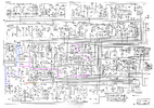
Assuming Q114 hasn't been plucked out, here are some numbers. The service manual does not show the SSB ALC voltages, but if you are going to follow the ALC path trying to troubleshoot it, this is what I think you can expect.
12w peak into 50ohm is 24.5v RMS, or 34.6v peak. The capacitive voltage divider C43/C44 (5pF/100pF) samples this 12w signal and provides a smaller RF voltage to the base of Q119. 34.6v peak * 5/(100+5) = 1.65v peak. With 12w out, we know the base of the ALC transistor should see peaks up to 1.65v.
This means the emitter would have to be set at about .95v (base - .7v) so that the transistor starts to conduct as soon as the RF waveform exceeds 12w peak (or 1.65v at the base).
The emitter voltage is set by the voltage divider R117 (18k) and VR104 (10k). To get .95v at the emitter, the pot would, in theory, have to be set to about 2450ohm with 8v from the supply.
The voltage levels may be a little different, but that's the basics of how it works. Each RF peak, the ALC transistor will briefly pull down on that pink trace causing Q138 to pulse on, and the RC stuff at Q114 smooths out those pulses with the required time constant so Q114 isn't pulsing the audio to the individual RF peaks.
Good luck!