thks! I ordered a Hantek osc..never used an osc..so how do I use it on this radio?On my Magnum 257 schematic it shows D25 as the VCO varactor, connected to L14. I would put a 'scope probe on TP3 to watch the VCO tuning voltage for a response to turning L14. Touching a probe tip directly to a varactor will change the circuit's capacitance. A 'scope probe's tip always has capacitance to ground. Usually enough to disrupt the circuit. An unshielded meter probe wire will nearly always disrupt a VCO circuit if it touches the varactor. A voltmeter is not a good tool for this. It's fine for setting L14 to the recommended TP3 tuning voltage in a working unit. Not so useful for troubleshooting. If any funny business appears on that tuning voltage at TP3, a 'scope will show it to you. A meter won't.
I never learned how to troubleshoot a PLL with a meter alone. Always had a 'scope at hand for that task.
The 10.695 crystal does not run in AM receive mode. It runs in AM transmit and for sideband receive and transmit both. Key the mike and see what it reads.
73

You are using an out of date browser. It may not display this or other websites correctly.
You should upgrade or use an alternative browser.
You should upgrade or use an alternative browser.
-
You can now help support WorldwideDX when you shop on Amazon at no additional cost to you! Simply follow this Shop on Amazon link first and a portion of any purchase is sent to WorldwideDX to help with site costs.
-
A Winner has been chosen for the 2026 July 4th Retevis RA89R Giveaway! Click Here to see who won!
HTX-10 pll problem?
- Thread starter codecxbox
- Start date

I would move the baseline to the bottom of the screen, set the vertical sensitivity to 1 Volt per cm with DC coupling, the sweep speed to 20 mS or so and then probe TP3.
73
73

Nomad, never used a osc..Tiny baby steps are welcome! but I can do whatever you say..its like learning to use a scopeI would move the baseline to the bottom of the screen, set the vertical sensitivity to 1 Volt per cm with DC coupling, the sweep speed to 20 mS or so and then probe TP3.
73

I did insert 4 to 6.5v on TP3 with a variable ps.. got great 10M signals at the speaker, thanks for SSB contest..also hooked up a TinySa on RF generator mode and the radio pickup a strong AM turning the L14 slug..10.240 crystal is strong and the 4.5 signal at pll pin 1 also
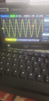
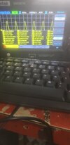
thks! crash coursed the osc..so this what I get..I would move the baseline to the bottom of the screen, set the vertical sensitivity to 1 Volt per cm with DC coupling, the sweep speed to 20 mS or so and then probe TP3.
73
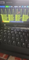
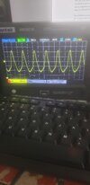
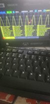
I have a 10.24ish signal on the XC1, seems it has a nice waveform.. I have 4.5 on Pin 1, but I not sure about the waveform..But I have no signal at the MFC1 10.695 big metal box. I did find a chipped I believe its a cap near the L6 can..but the over the top schematics are not clear..heres some pics..Also I probed TP3 with the scope and turned the slug and didnt see any reaction, just a flat line.
Attachments
thks! crash coursed the osc..so this what I get..
I have a 10.24ish signal on the XC1, seems it has a nice waveform.. I have 4.5 on Pin 1, but I not sure about the waveform..But I have no signal at the MFC1 10.695 big metal box. I did find a chipped I believe its a cap near the L6 can..but the over the top schematics are not clear..heres some pics..Also I probed TP3 with the scope and turned the slug and didnt see any reaction, just a flat line.
Attachments
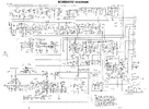
If it helps, here is a readable schematic. But I can't find T6 on it lol. Its in the alignment procedure, but I don't see it in the schematic.
Edit: The HTX-100 schematic used L instead of T for the cans, and in that schematic, L6 is by the crystal filter between L5 and L7. However, in the HTX-10 schematic, they used T for the cans and L6 is used elsewhere. I think they tried making one radio based on anothers schematic and things got messed up. I am going to guess that L6 is where R103 is in the HTX-10 schematic since the HTx-100 uses it as a choke in the same spot.
Edit: The HTX-100 schematic used L instead of T for the cans, and in that schematic, L6 is by the crystal filter between L5 and L7. However, in the HTX-10 schematic, they used T for the cans and L6 is used elsewhere. I think they tried making one radio based on anothers schematic and things got messed up. I am going to guess that L6 is where R103 is in the HTX-10 schematic since the HTx-100 uses it as a choke in the same spot.
Attachments
Last edited:
thks!!If it helps, here is a readable schematic. But I can't find T6 on it lol. Its in the alignment procedure, but I don't see it in the schematic.
Edit: The HTX-100 schematic used L instead of T for the cans, and in that schematic, L6 is by the crystal filter between L5 and L7. However, in the HTX-10 schematic, they used T for the cans and L6 is used elsewhere. I think they tried making one radio based on anothers schematic and things got messed up. I am going to guess that L6 is where R103 is in the HTX-10 schematic since the HTx-100 uses it as a choke in the same spot.
Here is the chipped part.If it helps, here is a readable schematic. But I can't find T6 on it lol. Its in the alignment procedure, but I don't see it in the schematic.
Edit: The HTX-100 schematic used L instead of T for the cans, and in that schematic, L6 is by the crystal filter between L5 and L7. However, in the HTX-10 schematic, they used T for the cans and L6 is used elsewhere. I think they tried making one radio based on anothers schematic and things got messed up. I am going to guess that L6 is where R103 is in the HTX-10 schematic since the HTx-100 uses it as a choke in the same spot.
Attachments
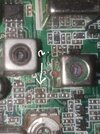
Also I am sorry..Should have said T6..the green capped canIf it helps, here is a readable schematic. But I can't find T6 on it lol. Its in the alignment procedure, but I don't see it in the schematic.
Edit: The HTX-100 schematic used L instead of T for the cans, and in that schematic, L6 is by the crystal filter between L5 and L7. However, in the HTX-10 schematic, they used T for the cans and L6 is used elsewhere. I think they tried making one radio based on anothers schematic and things got messed up. I am going to guess that L6 is where R103 is in the HTX-10 schematic since the HTx-100 uses it as a choke in the same spot.
I think it is C302, which I cant find it on the parts listIf it helps, here is a readable schematic. But I can't find T6 on it lol. Its in the alignment procedure, but I don't see it in the schematic.
Edit: The HTX-100 schematic used L instead of T for the cans, and in that schematic, L6 is by the crystal filter between L5 and L7. However, in the HTX-10 schematic, they used T for the cans and L6 is used elsewhere. I think they tried making one radio based on anothers schematic and things got messed up. I am going to guess that L6 is where R103 is in the HTX-10 schematic since the HTx-100 uses it as a choke in the same spot.
C302 is a 10nF 50V capacitor, but I do not think that is the problem. There are other caps on the same trace to ground. Not a bad idea to replace it if you can though.Also I am sorry..Should have said T6..the green capped can
I think it is C302, which I cant find it on the parts list


TP3 is the VCO charge pump and should be a flat line at about (correction, more than) 6.5v when set to 29.699MHz. It should only change when changing frequency or turning T14.thks! crash coursed the osc..so this what I get..
I have a 10.24ish signal on the XC1, seems it has a nice waveform.. I have 4.5 on Pin 1, but I not sure about the waveform..But I have no signal at the MFC1 10.695 big metal box. I did find a chipped I believe its a cap near the L6 can..but the over the top schematics are not clear..heres some pics..Also I probed TP3 with the scope and turned the slug and didnt see any reaction, just a flat line.
In the schematic, C302 is near the TX mixer. The only cans near there are T27, T28, T31, and T32, so I'm not sure what L6 even is in that radio. There is an L6 used as a choke by the 4.5MHz oscillator, but that appears to be a fixed value part, not a can, Hopefully someone knows what your L6 is.
What step of the alignment did you encounter this no signal issue on? Where 10.695MHz first appears in the alignment procedure (PLL section step 6) is also where you use TX instead of RX for the first time. Are you keying the radio? Don't forget the mini-jumper removal.
Last edited:
Sorry for the late response..and thnks..TP3 is at 7.38 volts and turning the T14 slug doesnt have any effect on voltage change..I can turn the slug and I do hear several signals from 11M to 10M..I attached my TinySa on low output mode at 28.00MhZ AM modulation at -30dB at the antenna port and I am able to receive a +30 when I turn the slug..but still the VFO is not doing anything..TP3 is the VCO charge pump and should be a flat line at about (correction, more than) 6.5v when set to 29.699MHz. It should only change when changing frequency or turning T14.
In the schematic, C302 is near the TX mixer. The only cans near there are T27, T28, T31, and T32, so I'm not sure what L6 even is in that radio. There is an L6 used as a choke by the 4.5MHz oscillator, but that appears to be a fixed value part, not a can, Hopefully someone knows what your L6 is.
What step of the alignment did you encounter this no signal issue on? Where 10.695MHz first appears in the alignment procedure (PLL section step 6) is also where you use TX instead of RX for the first time. Are you keying the radio? Don't forget the mini-jumper removal.
dxChat
- No one is chatting at the moment.