
You are using an out of date browser. It may not display this or other websites correctly.
You should upgrade or use an alternative browser.
You should upgrade or use an alternative browser.
-
You can now help support WorldwideDX when you shop on Amazon at no additional cost to you! Simply follow this Shop on Amazon link first and a portion of any purchase is sent to WorldwideDX to help with site costs.
-
A Winner has been chosen for the 2026 July 4th Retevis RA89R Giveaway! Click Here to see who won!
I need some crystal infomation for the 8719 pll chip
- Thread starter dss56
- Start date
It's the 1mW possible output power that has me worried.
Those types were for the original Xtal synthesis 23-channel radios to make up enough to mix together using Germanium transistors.
Once switched over to the PLL - 1mW can easily overload the inputs of any PLL. Yes, you need a baseline - it's why 11.325 works the way it does, but the Xtal itself - it's like putting in a live dead-carrier producing signal soldered in right at the tuning section and expecting the radio to sort it out.
The "tripler" concept was for using low-level and driving it to make multiple spurs - so to use a 1mW output Xtal - you need to make several changes to the "Exciter" side of the radio to obtain those needed spurs to make the Tripler - Triple - which uses a weaker output than a 1mW - I mean that is very similar to the older Walkie Talkie Xtal outputs - so as I research this - that can explain why you're having these issues. You need a waveform "shape" and output that let's the radio amplify the Xtals own "Resonance" - the problem you have is the amount of push the radio has to produce to make that Xtal even budge a Hertz...
A weaker signal equates to a type of sinusoidal wave shape that lets' a tuned circuit alter the resonance the Xtal presents. In this case it looks to be the Xtal sets the standard that the radio is gonna get - wether you like it or not.
So unless the board you are using to switch in these Xtals is truly isolating the resonance of one from the others - if one is still powered by the board - it will "Swamp" out any others because the PLL's own filter and filtration system used for the 40 channels (aka the 35-36MHz exciter range) favors the one signal that Xtal still produces and even though it's not amplified - you have one or three 1-mW capacity output types - yeah...it'll swamp out the others and favor the one the board is originally tuned for. You have to be sure that the Xtals are not mixing or any still power up and "leak" through.
You did try to use a different Xtal - the 11.47 one - and it would not "shift" Slide or move past go - so you do not collect $200 dollars and your still stuck...so that swap alone tells me that you will have to approach this type of Xtal differently - care to take a look at something from the past???
Remember that the output is greater than you need, so design a padded output network - not with resistors - but with capacitance. You can use Capacitors much like voltage dividers - only in this case you want to pare down the output of the Xtal to fit the input profile of the Tripler.

So what this tells me then, if you can't get past the 11.325 - and try a 11.47 or even the 11.12 (roughly) and you still get 11.325 to tune but have no control over the 11.4 or 11.12 tells me that in the issue of the tripling that needs to occur - the Xtals are not compatible with a weaker signal needed system.
Those types were for the original Xtal synthesis 23-channel radios to make up enough to mix together using Germanium transistors.
Once switched over to the PLL - 1mW can easily overload the inputs of any PLL. Yes, you need a baseline - it's why 11.325 works the way it does, but the Xtal itself - it's like putting in a live dead-carrier producing signal soldered in right at the tuning section and expecting the radio to sort it out.
The "tripler" concept was for using low-level and driving it to make multiple spurs - so to use a 1mW output Xtal - you need to make several changes to the "Exciter" side of the radio to obtain those needed spurs to make the Tripler - Triple - which uses a weaker output than a 1mW - I mean that is very similar to the older Walkie Talkie Xtal outputs - so as I research this - that can explain why you're having these issues. You need a waveform "shape" and output that let's the radio amplify the Xtals own "Resonance" - the problem you have is the amount of push the radio has to produce to make that Xtal even budge a Hertz...
A weaker signal equates to a type of sinusoidal wave shape that lets' a tuned circuit alter the resonance the Xtal presents. In this case it looks to be the Xtal sets the standard that the radio is gonna get - wether you like it or not.
So unless the board you are using to switch in these Xtals is truly isolating the resonance of one from the others - if one is still powered by the board - it will "Swamp" out any others because the PLL's own filter and filtration system used for the 40 channels (aka the 35-36MHz exciter range) favors the one signal that Xtal still produces and even though it's not amplified - you have one or three 1-mW capacity output types - yeah...it'll swamp out the others and favor the one the board is originally tuned for. You have to be sure that the Xtals are not mixing or any still power up and "leak" through.
You did try to use a different Xtal - the 11.47 one - and it would not "shift" Slide or move past go - so you do not collect $200 dollars and your still stuck...so that swap alone tells me that you will have to approach this type of Xtal differently - care to take a look at something from the past???
Remember that the output is greater than you need, so design a padded output network - not with resistors - but with capacitance. You can use Capacitors much like voltage dividers - only in this case you want to pare down the output of the Xtal to fit the input profile of the Tripler.
- There is also the issue of proper insertion...
I did not see this issue addressed but so you know - the AM line does have power to make the Xtal "fire" which changes the level of drive - so if your interface is not compensating for this effect, you have been warned. Recheck L59 stuff - make sure your insertion is ISOLATED electrically from the system.
I designed and built a tester rather nice one if must say so myself. It has numerous buffered or emitter follower output for the scope, freq counter, and spectrum analyzer. it was a bit of overkill but it came in handy many times.
if indeed we could conclude the crystal output was too much for the post-op stages, and I'm not there yet? I guess I would like to have to see the stage gain on a scope as well as there components on a spectrum. And I'm tired going to bed.
if indeed we could conclude the crystal output was too much for the post-op stages, and I'm not there yet? I guess I would like to have to see the stage gain on a scope as well as there components on a spectrum. And I'm tired going to bed.

 Well here goes posting pictures
Also I ordered some 11.3258 xtals from Mouser Electronics I got them this morning. Tried in radio and switch board and spot on work good. Like I said I had some of these but wanted to satisfy myself.
attached is the build spec sheet for the 11.3258 xtal and the package that i got them
notice the package says 30pf.


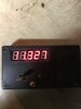
next 3 pictures are the 11.3258 AM USB/LSB showing the offsets when switched to Sideband


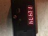
Next pics are the 11.4758 xtal for the upper forty channels above 40


So you can see with the 11.4758 xtal there is no Sideband shift for upper or lower ssb
Attachments
Last edited:
So xtals are in tolerance frequency wise.
Here is the spec sheet that the 11.4758 xtal was made to
Again thanks for every ones input and I'm going to try and have the 11.4758 xtal made to the 11.3258 specs and I'm sure they will work.
Here is the spec sheet that the 11.4758 xtal was made to
Again thanks for every ones input and I'm going to try and have the 11.4758 xtal made to the 11.3258 specs and I'm sure they will work.
Attachments
Last edited:
I don't know if they are still in business -Kens Electronics in Michigan sold a wide
assortment of crystals .
Might have what you need without having one made save $$$
assortment of crystals .
Might have what you need without having one made save $$$
Not to get into your buisness but where those special cuts and what did it cost for 3k crystals?Kens is still around Im looking for 500ea of 6 frequencies so 3000 xtals Just had 3k made for another project so I need a good amount.
these 6 freq xtals are for modding the 8719 pll with xtals and not doing the pin mod.
They work with the 8719 that has either the 11.1125 or the 11.3258 main xtal.
Some people dont like to mod the pll. These freqs were used in the Expo kits L and kit B all for the 8719pll
10.9625MHz
11.2625MHz
11.4125MHz
11.1758MHz
11.4758MHz
11.6258MHz
They work with the 8719 that has either the 11.1125 or the 11.3258 main xtal.
Some people dont like to mod the pll. These freqs were used in the Expo kits L and kit B all for the 8719pll
10.9625MHz
11.2625MHz
11.4125MHz
11.1758MHz
11.4758MHz
11.6258MHz
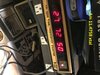
Here is a picture of the 3 xtal switch board also have a 6 xtal version all electronic diode switching no wire length oscillation. Switch can be mounted anywhere in radio.
3 xtal board 3 way toggle switch. 6 xtal board needs a 6 position rotary switch.
So its just jury rigged for now to do test with the sample xtals i received and I guess were not made correctly!!
Board is about 1.75 square
Large xtal is the 11.3258
small xtal is the 11.4758
I did not put a xtal in 3rd slot as i'm just testing right now
Hold on second...

Are you aware that as you increase the pF value of the Xtal, the ability for it to shift in frequency is less?

You have 30pF Xtals - you said you got 20pF - now you have a problem with 10X the requirement.
I need some crystal infomation for the 8719 pll chip post #5
I need some crystal infomation for the 8719 pll chip post #6
For a quick lesson - go here
Might save us a lost effort in shifting ...
As said before the less pF the easier it is to exert an external circuit L, C or R to change the frequency.
The package shows 30pF
You'll need a hammer to move them. The output is a lot more powerful than a 7 ~12pF typically found in earlier CB's...
The board you show us here

Is not the same as shown in post #40.
I do understand that you are having problems with "shift" and slide to make SSB work.
Ok, with the two above designs - they use a "Buss" for return and it can also provide power to the Xtals.
Remember the schematic of the 148, there is a reason for that L59 direct line. But unless you find a better less inductive method - like using a riser card fixed at a given height so you can properly ground the Xtals to foil board ground then to switch the Xtals in or out - you have a lot of inductance and no matter the effort, a 30pF Xtal is gonna fight a 3pF max varactor trying to exert it's capacitance on it.
See attached...PDF...
Attachments
Last edited:
There is also the issue of proper insertion...
- I did not see this issue addressed but so you know - the AM line does have power to make the Xtal "fire" which changes the level of drive - so if your interface is not compensating for this effect, you have been warned. Recheck L59 stuff - make sure your insertion is ISOLATED electrically from the system.
That's the USB line going to L59. And it is only powered in USB mode, and I don't know why they didn't isolate it with a .01uF cap like the AM and LSB mode coils.
If you are going to build a crystalplex circuit for an SSB radio like a Washington, I would suggest using the Galaxy Viagra A board as a template, it has individual alignment coils for each crystal for each upper or lower band, and individual "Clarifier" diodes for each crystal too.
http://www.cbtricks.com/radios/galaxy/viagra/index.htm

The Viagra B board uses an MC145106DW (SMD version).
I have one of each I bought to sample/evaluate about 6 or 7 years ago from RF Parts.
Last edited:
...It was a busy day when I posted that...
Thanks for rescuing the thread - but the one effect of L59 I was trying to mention is that it provides a method of return for signal that does interact weakly with the others - it's what I found in resistance checks of the Xtal to see if I had a poorly or otherwise weak signal when it came to having got a 148 in for repair that wouldn't stay locked. The Xtal in question (Read:Thread) didn't seem to want to play well with others so if anything - I'm looking at the design of L22, L23 ok they follow suit, then BAM L59 number comes out of nowhere and numbered that way for no particular reason - until I looked into a problem with a Voicelock that was really touchy. Did not know if anyone else caught that - good to know I'm not the only one...
It was how I found out the Xtals need somewhere to send part of their signal so they can even stay in tune let alone resolve isolation issues with someone's body capacitance affecting the "Drift" the radio has when someone simply tunes in an operator and has to "Dance" the control to make it work.
Makes for an interesting train of thought trying to sort it all out and seeing their early efforts in the design when knowing they simply wanted to remove the charge off a plate...
Attachments
Last edited:
I have always aligned the USB coil first as a reference, because it is more directly connected to the crystal, then the AM then LSB last. It is, after all, an 11.3258 MHz crystal.
