The frequency stability of a radio is always of concern. Manufacturers go a long way to improve the performance of a radio but when it comes to frequency stability it leaves a lot to be desired. The purchase of an optional stabilised oscillator is always required to get the performance you want. These units can range from about $100.00 to well over $250.00 depending on where you look.
There is another option; it is called a constant temperature thermistor heater. This device when attached to the crystal body can provide a constant crystal temperature. It is wise to select a thermistor that does not exceed 60°C or the crystal oscillator reliability could be affected. In this instance a 50°C unit was selected, it will stabilise the temperature without stressing the crystal.
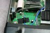
The following images show the construction and installation of one of these crystal heaters.
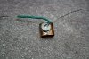
You start by picking an old crystal, the same size as the one in the radio. You cut some copper shim to the height of the crystal and wrap it once around the crystal body. Trim any access copper and shape it until the crystal fits snug and tight into it. The next step is to de-solder one leg of the thermistor and soldering the body of the thermistor to the flat side of the copper shim. Place some heatshrink tubing over the exposed leg of the thermistor and solder a piece of wire to the copper shim.
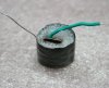
Wrap some packing foam, polystyrene or other insulating material around the copper shim and secure it with some tape.
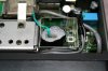
Place the assembly on the radio crystal, solder the wire connected to the copper shim to the inside wall of the compartment, feed the thermistor wire through the vacant hole in the compartment wall, place some foam on top of the assembly to thermally insulate the heater from the rest of the radio and replace the oscillator cover.
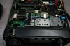
Extend the heater wire so it can be connected to the power source.
The next step is to find a power source and even though the thermistor temperature is fairly constant it may fluctuate with varying voltages so the best source is a regulated supply.
Before connecting the power, ensure there are no short circuits to chassis and the resistance measures about 50? between chassis and the wire to be connected to the power rail.
The current requirement is about 140mA but for only a short time so it can be connected directly to the on board 8V regulator. As the thermistor temperature stabilises the current consumption will drop to below 50mA.
Power up the radio, allow the thermistor the heat up for about 1 minute and realign the crystal frequency. Stability should be in the order of .5 ppm or better and will make a noticeable difference on VHF and UHF where stability has the greatest impact.
This heater project is not restricted to this model of radio and can be applied to any piece of equipment where thermal stability is required.
The thermistor used for this project is the RL3006-50-50-25-PTO and is available from RS Components, Mouser Electronics and other suppliers for about $1.00 - $2.00, a very cheap alternative to the expensive commercial product.
See attached pictures below....
Thanks to Adriaan de Bruyn for the Modification and pictures
73
Jeff
There is another option; it is called a constant temperature thermistor heater. This device when attached to the crystal body can provide a constant crystal temperature. It is wise to select a thermistor that does not exceed 60°C or the crystal oscillator reliability could be affected. In this instance a 50°C unit was selected, it will stabilise the temperature without stressing the crystal.
The following images show the construction and installation of one of these crystal heaters.
You start by picking an old crystal, the same size as the one in the radio. You cut some copper shim to the height of the crystal and wrap it once around the crystal body. Trim any access copper and shape it until the crystal fits snug and tight into it. The next step is to de-solder one leg of the thermistor and soldering the body of the thermistor to the flat side of the copper shim. Place some heatshrink tubing over the exposed leg of the thermistor and solder a piece of wire to the copper shim.
Wrap some packing foam, polystyrene or other insulating material around the copper shim and secure it with some tape.
Place the assembly on the radio crystal, solder the wire connected to the copper shim to the inside wall of the compartment, feed the thermistor wire through the vacant hole in the compartment wall, place some foam on top of the assembly to thermally insulate the heater from the rest of the radio and replace the oscillator cover.
Extend the heater wire so it can be connected to the power source.
The next step is to find a power source and even though the thermistor temperature is fairly constant it may fluctuate with varying voltages so the best source is a regulated supply.
Before connecting the power, ensure there are no short circuits to chassis and the resistance measures about 50? between chassis and the wire to be connected to the power rail.
The current requirement is about 140mA but for only a short time so it can be connected directly to the on board 8V regulator. As the thermistor temperature stabilises the current consumption will drop to below 50mA.
Power up the radio, allow the thermistor the heat up for about 1 minute and realign the crystal frequency. Stability should be in the order of .5 ppm or better and will make a noticeable difference on VHF and UHF where stability has the greatest impact.
This heater project is not restricted to this model of radio and can be applied to any piece of equipment where thermal stability is required.
The thermistor used for this project is the RL3006-50-50-25-PTO and is available from RS Components, Mouser Electronics and other suppliers for about $1.00 - $2.00, a very cheap alternative to the expensive commercial product.
See attached pictures below....
Thanks to Adriaan de Bruyn for the Modification and pictures
73
Jeff