
This modification has been tested and confirmed for “USA models ONLY”, including those with the most recent firmware from revisions from ICOM as of 06-30-2008…
Extended Transmit Frequency Coverage Ranges:
137MHz. to 174MHz. (Left Side)
400MHz. to 470MHz. (Right Side)
Modification:
That's it your all done!
There is no reset required; however I strongly recommend that you perform a “full reset” prior to programming and using the radio.
Extended Transmit Frequency Coverage Ranges:
137MHz. to 174MHz. (Left Side)
400MHz. to 470MHz. (Right Side)
Modification:
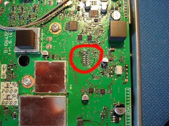
- Remove the top cover. (This is the side with the serial number sticker)
- Locate the jumper panel as shown in the photo. (This is the one to the left of the white j-tag firmware uploading connector and to the right of the “VIII” notation on the circuit board)
- Take note of the jumpers currently in place. On models that the modification has been successful, there have been NO jumpers on the right side of the jumper panel. On the left side of the jumper panel, ONLY jumpers “5”, “6”, & “7” were in place from the factory.
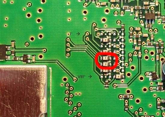
- Remove the ONLY the jumpers in positions “5” & “6” counting from the top down on the left side of the jumper panel.
- Check for loose solder pieces, clean with compressed air and reinstall the top cover.
That's it your all done!
There is no reset required; however I strongly recommend that you perform a “full reset” prior to programming and using the radio.
