
Hi Guys,
I've been having fun experimenting with my Galaxy DX-979.
I wanted to increase the frequency coverage, but I wasn't happy with the usual switches that modify the settings fed to the PLL. Mostly because I don't care for the frequencies being out of order and having to refer to a chart. I do have a matching external frequency counter, but it's still inconvenient having the frequencies scattered about.
I decided to see if there was something I could do easily to make it more convenient.
I enjoy doing small electronics projects and I've been playing with the Arduino series of microcontrollers. They're cheap, easy to program and readily available. All one really needs to do is turn power on or off to seven wires to control the PLL frequency, and turning things on and off is duck soup for an Arduino, so I decided to see if I could combine the two. I also decided to include a four line, twenty character LCD display. They are also cheap, readily available and easy to hookup and program for, and I thought it would be nice to be able to display some information, especially if one doesn't have a frequency counter.
I used an Arduino Uno as it seemed the best match for the project. I would've liked to use an Arduino Micro Pro, but the sketch is a bit large for it (that version of Arduino builds some overhead in as it can function as a USB keyboard or mouse and you can't keep it from building that overhead in) and it doesn't contain a full 8 bit port I can address quickly and easily. As I experiment I'll revisit using it, but for now I just wanted to play quickly and easily and the Uno was more than capable.
I used a four line, twenty character display as they're the only ones I purchase since they are roughly the same price as a two line, sixteen character and it seems you always need to display more than you have the capacity to.
I debated on what to use for a channel selector. The obvious choice is to use the radio's channel selector, but interfacing to and programming for it will take a little effort and again, I was simply in a hurry to play so I looked for something easier. I thought about a simple five button keypad (up, down, left, right and enter). It would be easy to move up or down a channel at a time and you could make the left and right arrows move up or down ten channels to move through them quickly very easily. The only real issue was that when you shut the radio off and turn it back on it's always going to start at whatever you hard code the starting channel to be. Not a big deal, but I just didn't like it. I finally decided that a 10K potentiometer would fit the bill. When a potentiometer is hooked up to one of the Arduino's analog inputs it will divide the 5v being supplied to it into 1,023 steps so it's very easy to simply divide 1,023 by the number of frequencies and then just say if the analog read value is between x and x generate frequency x and display it's associated text to the LCD. The bonus is that when you turn the radio off and back on you will still be on the same frequency that you last left it at. A 10K single turn pot puts the frequencies pretty close together, but it's not bad. I have a three turn pot on order though. Though expensive, they also make continuous turning pots that would allow one to cycle through all the frequencies and then start over again at the lowest frequency without having to turn back the other way when the highest frequency was reached. In my limited experiments thus far though, the single turn pot has been fine.
I didn't want to hack up my radio, why I dunno, I got it used and cheap and it's not that expensive to start with, but it's just my preference to take the least invasive approach. Everything needed is contained in the wiring harness coming from the channel selector to the main board, but again I didn't want to hack up my radio. After a little research I found the connector is a JST (Japan Solderless Terminal) PH series, 2.0mm spacing, single inline 10 pin. Unfortunately I couldn't find a source for these pre-made Stateside. I could find the terminals and housings but you need an expensive crimping tool to use them. I found some pigtails on eBay that come with the female end terminals already crimped on and in a housing. The male end is a pc solder mount, but it's easy enough to solder the other end of the leads on to it (I used liquid electrical tape to paint the exposed solder tabs). The only real issue was that the vendor was in Hong Kong and it took almost a MONTH for them to arrive! The board end of the wiring harness is under the channel selector pcb, so it's not readily accessible so I simply left it hooked up to the board and plugged the male of the cable I made into it.
The Arduino runs on 5v and the PLL on 8, so I installed a level shifter on the PLL lines (a cheap device also readily available on eBay). 10K pull down resistors were also installed between the PLL lines and ground to pull the lines to a stable normally low state.
Here's a picture of my Arduino development board. The LCD is in the upper left, the 10K pot in the top right and the Arduino Uno is in the lower right. The device in the lower left is an Arduino Micro Pro that's unused in this application.
http://www.worldwidedx.com/data/photos/l/3/3301-1422584366-ca835d6e727b2979365ef1e675c4975b.jpg
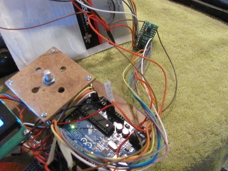
Here's a pic of the level shifter.
http://www.worldwidedx.com/data/photos/l/3/3302-1422584382-d3aa1d893f76336c0915df226054b5af.jpg
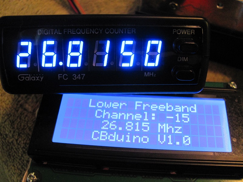
Here's a picture of the LCD display and the external frequency counter confirming the frequency. Note it displays what band you are in (in this case the lower freeband), the channel relative to CB channel #1 and the frequency.
http://www.worldwidedx.com/data/photos/l/3/3303-1422584389-3b7c467452505affb47d76bb6b0a28cd.jpg
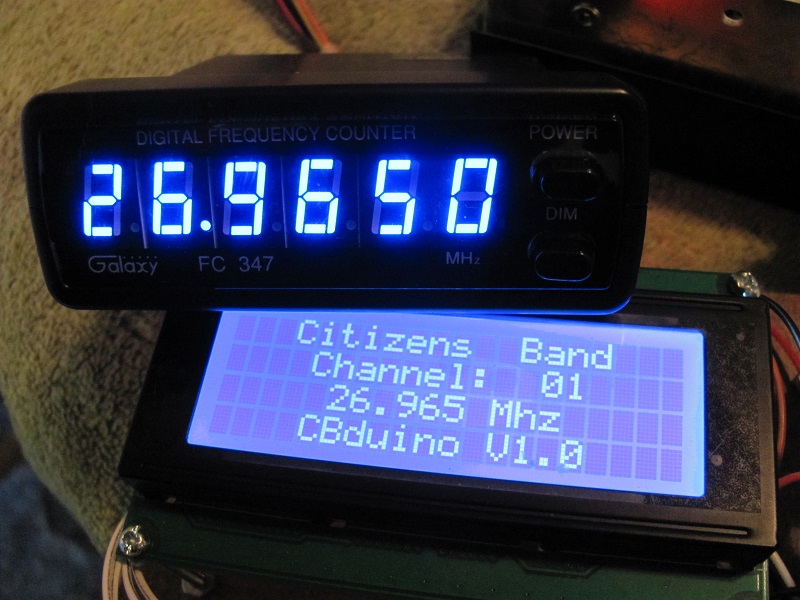
Here's a picture of it on CB channel 1 - note the band display has changed.
http://www.worldwidedx.com/data/photos/l/3/3304-1422584396-6b099e089545bfe78c2f8ea1c588ed40.jpg
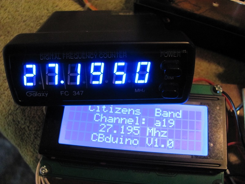
There are also channels between some standard CB channels, these channels were originally used for remote control toys and other such devices. Here's a pic showing one of those channels being tuned in - note the "a" for additional displayed before the channel number.
http://www.worldwidedx.com/data/photos/l/3/3305-1422584402-dab856ab92224dad3fc0afd628fd6ddc.jpg
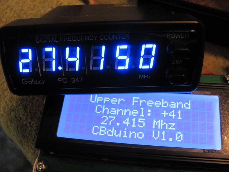
Here's a picture showing the change from CB to the upper freeband at 27.4155, note again the band designation change.
http://www.worldwidedx.com/data/photos/l/3/3306-1422584411-3baa6c1e6c302b95c30e5b2c3079c8e4.jpg
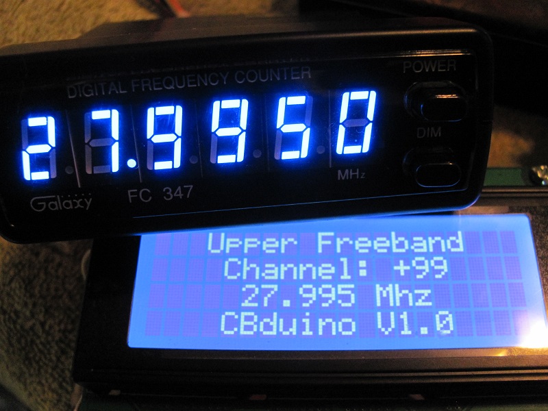
This pic is just showing the top frequency. This radio is actually capable of frequencies into the 10 meter ham band, but I consciously programmed it to not go beyond 27.995.
http://www.worldwidedx.com/data/photos/l/3/3307-1422584417-cac83a6b3c84307e3e526873b1e2bb7e.jpg
This radio, and others such as the Galaxy 929, have a slightly different crystal in them at X3 so they don't go as low as other radios such as the Galaxy 959, but they go higher. Since any frequency above 27.995 is unusuable, and actually one probably should keep a few channels below to avoid any possible chance of causing interference on the neighboring ham band, the frequency spread of the 959 may be preferable. I have a crystal from a 959 on the way and will test it and report back once it arrives. The crystal change will require some tweaking to the Arduino sketch but it won't take much effort and will probably allow the CBduino to be used with the more popular 959 radios (I say probably because I don't have one to experiment with).
The project is a mess right now, just a rats nest of long wires and the such. I'll work on shortening them up. I'm hoping the Arduino can be left in the radio case, if so then one would just need to run 7 wires out of the case, four for the LCD display and three for the potentiometer. A decent quality network cable would probably be an readily available 8 conductor cable to use for this. The LCD and pot would fit in a fairly small external case.
In the future I would like:
*) To get this working with the physically much smaller Arduino Micro Pro.
*) To interface to the channel selector. I'm thinking three sets of 40 channels would work out well. The Arduinos have eeprom memory that is rated at 100,000 read write cycles, so I'm thinking a set change flag could be written to the eeprom. This would create continuous tuning with no physical channel set switches needed. We could read the channel setting and reorder the channels so they are sequential.
*) Interface to a three digit LED for channel display for radios without a frequency display.
*) I may revisit the keypad idea also, I'm thinking interesting things could be done with a 12 or 16 key keypad. Possibly a search function? Maybe monitor the speaker voltage - turn up the squelch so the speak is silent, then increment the channel and check the speaker for sound, if sound stop, if no sound then increment the channel and check the speaker again, etc.? Favorite channels could also be assigned to keys. Receive modifications, RFX amplifier on/off, etc. could also all be assigned to keys.
All in all, this could be a fun project for a while yet!
For now, I'm quite happy - the initial incarnation is working well and so far everything has been plug and play.
I'll update as I play further...any questions or comments are most welcome.
I'll post the Arduino sketch shortly after I have a little more time to bug test.
Take care,
Steve
I've been having fun experimenting with my Galaxy DX-979.
I wanted to increase the frequency coverage, but I wasn't happy with the usual switches that modify the settings fed to the PLL. Mostly because I don't care for the frequencies being out of order and having to refer to a chart. I do have a matching external frequency counter, but it's still inconvenient having the frequencies scattered about.
I decided to see if there was something I could do easily to make it more convenient.
I enjoy doing small electronics projects and I've been playing with the Arduino series of microcontrollers. They're cheap, easy to program and readily available. All one really needs to do is turn power on or off to seven wires to control the PLL frequency, and turning things on and off is duck soup for an Arduino, so I decided to see if I could combine the two. I also decided to include a four line, twenty character LCD display. They are also cheap, readily available and easy to hookup and program for, and I thought it would be nice to be able to display some information, especially if one doesn't have a frequency counter.
I used an Arduino Uno as it seemed the best match for the project. I would've liked to use an Arduino Micro Pro, but the sketch is a bit large for it (that version of Arduino builds some overhead in as it can function as a USB keyboard or mouse and you can't keep it from building that overhead in) and it doesn't contain a full 8 bit port I can address quickly and easily. As I experiment I'll revisit using it, but for now I just wanted to play quickly and easily and the Uno was more than capable.
I used a four line, twenty character display as they're the only ones I purchase since they are roughly the same price as a two line, sixteen character and it seems you always need to display more than you have the capacity to.
I debated on what to use for a channel selector. The obvious choice is to use the radio's channel selector, but interfacing to and programming for it will take a little effort and again, I was simply in a hurry to play so I looked for something easier. I thought about a simple five button keypad (up, down, left, right and enter). It would be easy to move up or down a channel at a time and you could make the left and right arrows move up or down ten channels to move through them quickly very easily. The only real issue was that when you shut the radio off and turn it back on it's always going to start at whatever you hard code the starting channel to be. Not a big deal, but I just didn't like it. I finally decided that a 10K potentiometer would fit the bill. When a potentiometer is hooked up to one of the Arduino's analog inputs it will divide the 5v being supplied to it into 1,023 steps so it's very easy to simply divide 1,023 by the number of frequencies and then just say if the analog read value is between x and x generate frequency x and display it's associated text to the LCD. The bonus is that when you turn the radio off and back on you will still be on the same frequency that you last left it at. A 10K single turn pot puts the frequencies pretty close together, but it's not bad. I have a three turn pot on order though. Though expensive, they also make continuous turning pots that would allow one to cycle through all the frequencies and then start over again at the lowest frequency without having to turn back the other way when the highest frequency was reached. In my limited experiments thus far though, the single turn pot has been fine.
I didn't want to hack up my radio, why I dunno, I got it used and cheap and it's not that expensive to start with, but it's just my preference to take the least invasive approach. Everything needed is contained in the wiring harness coming from the channel selector to the main board, but again I didn't want to hack up my radio. After a little research I found the connector is a JST (Japan Solderless Terminal) PH series, 2.0mm spacing, single inline 10 pin. Unfortunately I couldn't find a source for these pre-made Stateside. I could find the terminals and housings but you need an expensive crimping tool to use them. I found some pigtails on eBay that come with the female end terminals already crimped on and in a housing. The male end is a pc solder mount, but it's easy enough to solder the other end of the leads on to it (I used liquid electrical tape to paint the exposed solder tabs). The only real issue was that the vendor was in Hong Kong and it took almost a MONTH for them to arrive! The board end of the wiring harness is under the channel selector pcb, so it's not readily accessible so I simply left it hooked up to the board and plugged the male of the cable I made into it.
The Arduino runs on 5v and the PLL on 8, so I installed a level shifter on the PLL lines (a cheap device also readily available on eBay). 10K pull down resistors were also installed between the PLL lines and ground to pull the lines to a stable normally low state.
Here's a picture of my Arduino development board. The LCD is in the upper left, the 10K pot in the top right and the Arduino Uno is in the lower right. The device in the lower left is an Arduino Micro Pro that's unused in this application.
http://www.worldwidedx.com/data/photos/l/3/3301-1422584366-ca835d6e727b2979365ef1e675c4975b.jpg
Here's a pic of the level shifter.
http://www.worldwidedx.com/data/photos/l/3/3302-1422584382-d3aa1d893f76336c0915df226054b5af.jpg
Here's a picture of the LCD display and the external frequency counter confirming the frequency. Note it displays what band you are in (in this case the lower freeband), the channel relative to CB channel #1 and the frequency.
http://www.worldwidedx.com/data/photos/l/3/3303-1422584389-3b7c467452505affb47d76bb6b0a28cd.jpg
Here's a picture of it on CB channel 1 - note the band display has changed.
http://www.worldwidedx.com/data/photos/l/3/3304-1422584396-6b099e089545bfe78c2f8ea1c588ed40.jpg
There are also channels between some standard CB channels, these channels were originally used for remote control toys and other such devices. Here's a pic showing one of those channels being tuned in - note the "a" for additional displayed before the channel number.
http://www.worldwidedx.com/data/photos/l/3/3305-1422584402-dab856ab92224dad3fc0afd628fd6ddc.jpg
Here's a picture showing the change from CB to the upper freeband at 27.4155, note again the band designation change.
http://www.worldwidedx.com/data/photos/l/3/3306-1422584411-3baa6c1e6c302b95c30e5b2c3079c8e4.jpg
This pic is just showing the top frequency. This radio is actually capable of frequencies into the 10 meter ham band, but I consciously programmed it to not go beyond 27.995.
http://www.worldwidedx.com/data/photos/l/3/3307-1422584417-cac83a6b3c84307e3e526873b1e2bb7e.jpg
This radio, and others such as the Galaxy 929, have a slightly different crystal in them at X3 so they don't go as low as other radios such as the Galaxy 959, but they go higher. Since any frequency above 27.995 is unusuable, and actually one probably should keep a few channels below to avoid any possible chance of causing interference on the neighboring ham band, the frequency spread of the 959 may be preferable. I have a crystal from a 959 on the way and will test it and report back once it arrives. The crystal change will require some tweaking to the Arduino sketch but it won't take much effort and will probably allow the CBduino to be used with the more popular 959 radios (I say probably because I don't have one to experiment with).
The project is a mess right now, just a rats nest of long wires and the such. I'll work on shortening them up. I'm hoping the Arduino can be left in the radio case, if so then one would just need to run 7 wires out of the case, four for the LCD display and three for the potentiometer. A decent quality network cable would probably be an readily available 8 conductor cable to use for this. The LCD and pot would fit in a fairly small external case.
In the future I would like:
*) To get this working with the physically much smaller Arduino Micro Pro.
*) To interface to the channel selector. I'm thinking three sets of 40 channels would work out well. The Arduinos have eeprom memory that is rated at 100,000 read write cycles, so I'm thinking a set change flag could be written to the eeprom. This would create continuous tuning with no physical channel set switches needed. We could read the channel setting and reorder the channels so they are sequential.
*) Interface to a three digit LED for channel display for radios without a frequency display.
*) I may revisit the keypad idea also, I'm thinking interesting things could be done with a 12 or 16 key keypad. Possibly a search function? Maybe monitor the speaker voltage - turn up the squelch so the speak is silent, then increment the channel and check the speaker for sound, if sound stop, if no sound then increment the channel and check the speaker again, etc.? Favorite channels could also be assigned to keys. Receive modifications, RFX amplifier on/off, etc. could also all be assigned to keys.
All in all, this could be a fun project for a while yet!
For now, I'm quite happy - the initial incarnation is working well and so far everything has been plug and play.
I'll update as I play further...any questions or comments are most welcome.
I'll post the Arduino sketch shortly after I have a little more time to bug test.
Take care,
Steve

") So far it has been a fun project!
So far it has been a fun project!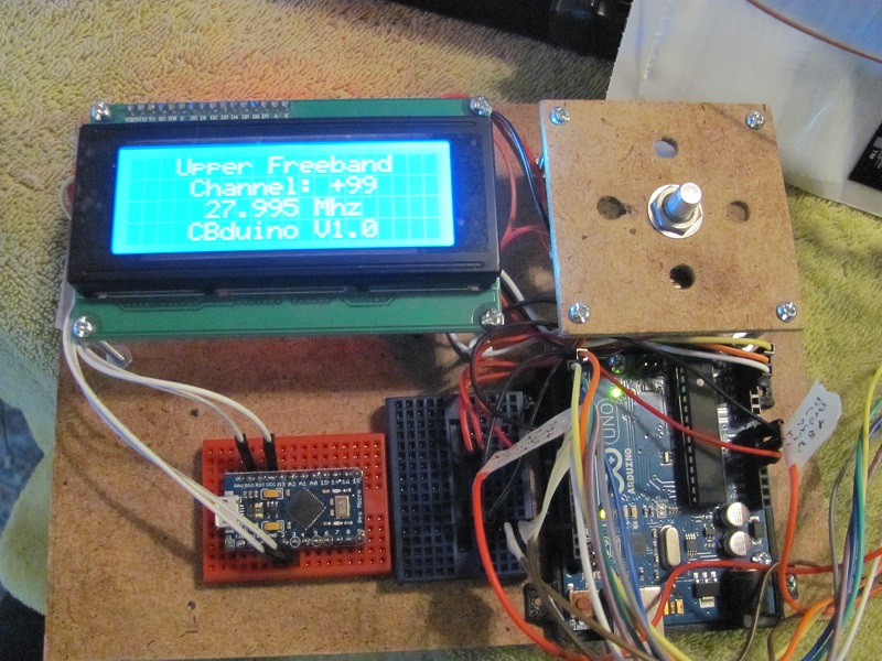